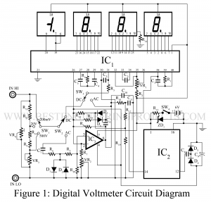
A digital voltmeter (DVM) Circuit displays measurements of AC or DC voltage as discrete numerals instead of a pointer deflection on a continuous scale as in analog instruments. Digital Voltmeter Circuit is a versatile and accurate instrument that is employed in many laboratory measurement applications. Because of the development and perfection of the IC modules, the size, power requirement, and cost of the digital voltmeter as been drastically reduced, and therefore, digital voltmeter circuits can actively compete with the conventional analog instruments in price, portability, and accuracy. Here, in this…
Read MoreCategory: Digital Electronics Projects
In the category “Digital Electronics Projects” various circuit is designed and verified using different gates and digital IC.
Electronic Code Lock Circuit
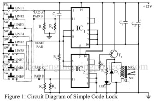
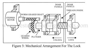
Using codes for security has been a popular trend recently. A similar type of electronic project is presented right below called the electronic code lock circuit which ensures the use of four digits in the code locking process and these codes are keyed in remotely. The code can be unlocked easily by pressing the right keys and if someone presses the wrong keys, it resets the lock automatically. The complete phenomenon of the electronic code lock systems has been described briefly in the further paragraph. Description and Working of Electronic…
Read MoreWater Level Indicator Circuit
One of the most common circuits in the market is the water level indicator. But most of these circuits fault corrosion of metal electrodes due to electrolytic reaction. This fault can be minimized effectively by using alternating current instead of direct current supply. Here we design and verify a circuit called electrolysis proof water level indicator using a COMOS IC which has profitably exploited the normally unused property of CMOS devices. Other Water level indicators and controller circuits posted on bestengineeringprojects.com Ultrasonic Water Level Meter Water Level Indicator Circuit using…
Read MoreMains Supply Interruption Indicator Circuit
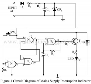
The Mains Supply interruption indicator circuit can be used in applications where it is necessary to know whether the mains supply has been continuous or not. The circuit mains supply interruption indicator will be useful for monitoring mains supplies to recording equipment, especially in the recording of computer software tapes, where the slightest interruption in the mains supply will cause an error in the data being recorded. It can also be used with digital clocks working on mains. An interruption in the mains supply will cause an LED to flash…
Read MoreLight operated internal door latch
Previously, we have posted light controlled digital fan regulator, with which we can control the speed of the fan remotely from the bed with the help of a torchlight. Now, here is another light-operated project which can also operate remotely from the bed with a torchlight. The group electronics hobbyist at Best Engineering Projects designed and verified a very unique electronic circuit light operated internal door latch with which one can close or open the door of your room remotely.” Check out other security-related projects posted on bestengineeringproject.com Car Lock…
Read MoreUniversal Digital Power Supply Circuit
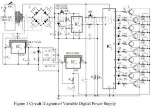
Various types of power supply circuits like fixed regulated, variable power supply, and stabilized power supply circuits are already published on bestengineeringproject.com. Most of us hear about the universal power supply, it is a power supply unit that provides almost all standard power supply. How’s that if we combine a universal power supply and a digital control technology. Here, the innovative group of Dreamlover Technology designed and verified a universal power supply circuit with the facility of digital control. The unit universal digital power supply provides a variable, fluctuation-free and…
Read MoreLight Controlled Digital Fan Regulator Circuit
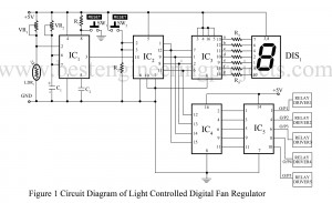
Mans are born of habit, and we all want comfortable. At night while sleeping we often switch of the light. But sometime we used to increase or decrease the speed of fan. And it is very difficult to trace the switch board in a dark room at night and to wake-up from bed is also irrigative. By keeping this problem in mind the group of electronics geek at Dreamlover technology designed and verified a electronics project called light controlled digital fan regulator circuit. You can also check this awesome project IR…
Read MoreFrequency Generator and Divider circuit
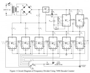
What are Frequency Generator and Divider Circuit? A frequency generator is a circuit that generates a frequency and a divider circuit divides the generated frequency with various factors to get different frequency values. Various assembled frequency generators and divider circuits are available in the market but they are quite expensive to buy. The group of electronics geeks at dream lover technology designs a low-cost square wave signal generator and divider circuit. The frequency of 1 Hz, 10 Hz, 100 Hz, 1 kHz, 100 kHz, and 1 MHz are obtained at…
Read MoreAutomatic Gate Light Circuit
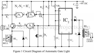
While returning home on a cold winter night it can be really frustrating if one is unable to unlock the gate due to insufficient light. A simple, economic yet reliable solution to the problem is provided by the project “Automatic Gate Light Circuit”. When it is quite dark, a slightly pressure on the bell switches the gate lights on for a preset interval of time. The project automatic gate light circuit is also a valuable addition to domestic security arrangements as it deters unwelcome caller. Description of Automatic Gate Light…
Read MoreAutomatic Suction Tank Motor Controller
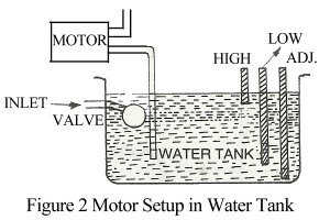
Many of us use water pumps for drawing water from an underground tank. Whenever the water level in the tank goes low we have to switch ‘off’ the motor and when it reaches a high level we have to switch ‘on’ the motor. The circuit automatic suction tank motor controller given here solves this problem. The truth table for the digital circuit of automatic suction tank motor controller Condition H L Y Remark Empty tank 0 0 0 Water is filled up to ‘L’ 0 1 0 Full tank 1…
Read More