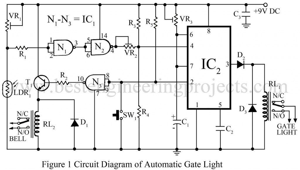
While returning home on a cold winter night it can be really frustrating if one is unable to unlock the gate due to insufficient light. A simple, economic yet reliable solution to the problem is provided by the project “Automatic Gate Light Circuit”. When it is quite dark, a slightly pressure on the bell switches the gate lights on for a preset interval of time. The project automatic gate light circuit is also a valuable addition to domestic security arrangements as it deters unwelcome caller.
Description of Automatic Gate Light Circuit
N1 and N2 if IC1 (CD4011) are wired as inverter gates. When light falls on the LDR, its resistance becomes low, so the output level of N1 at pin 3 becomes high whereas output level of gate N2 at pin 4 becomes low.
VR1 is set so as to switch on the gate light. Switch SW1 is pressed when the light falling on the LDR is very low (at night). VR2 is set for about 0.25V at pin 4 of IC2 when light falls on the LDR and about 0.45V when no light falls on the LDR. Gate light is switched on as soon as switch SW1 is pressed provided no light falls on the LDR. And it remains on for a preset interval of time, which is set with VR3. Gate N3 is also wired as an inverter gate.
Its output is high for the time in which SW1 is pressed. Transistor T1 operates relay RL1 which in turn operates the bell. Operation of bell is independent of the light falling on the LDR, i.e. it can be operated both in day and at night whereas the gate light operates only at night.

In stand-by state, i.e. when both the relays are inactive, the current consumption is as low as 6mA. The maximum current rating of the relay should not exceed 200mA. The gate light can be latched from inside the house by simple switching on the existing gate-light switch if it is connected in parallel with the relay contacts (relay RL2). Capacitor C3 should be soldered on the PCB as close as possible to the supply pins of IC1. The LDR should face downwards so as to prevent all other night light falling on it.
PARTS LIST OF AUTOMATIC GATE LIGHT CIRCUIT
|
Resistor (all ¼-watt, ± 5% Carbon) |
|
R1, R3 = 100 KΩ R2 = 1.8KΩ R4 = 8.2 KΩ R5 = 10 KΩ VR1 = 4.7 KΩ VR2 = 47 KΩ VR3 = 2.2 MΩ |
|
Capacitors |
|
C1 = 220 µF/35V C2, C3 = 0.01 µF |
|
Semiconductors |
|
IC1 = CD4011 IC2 = 7555 D1, D2, D3 = 1N4001 T1 = SL100 |
|
Miscellaneous |
|
SW1 = Push-To-On Switch LDR1 RL1 = 9V, 100Ω Relay RL2 = 6V, 100Ω Relay |
I am proud of your site, & interested.