The circuit 1/86400 Hz frequency generator provides one clock pulse every 24 hours from a 1 Hz input clock pulse source, which is commonly available through a digital clock. It can be used to provide am/pm indication in those digital clocks which do not have this facility, or it may be utilized to advance the date of an electronic calendar every day. It can also be used to trigger an alarm at a determined time without fail. Circuit Description of 1/86400 Hz Frequency Generator The present circuit 1/86400 Hz frequency…
Read MoreCategory: Digital Electronics Projects
In the category “Digital Electronics Projects” various circuit is designed and verified using different gates and digital IC.
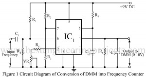
Frequency Counter Using Digital MultiMeter
As being electronic hobbyists we love to design and verify various types of circuits, we often have to measure the output frequency. The device which is used for this purpose is called the frequency counter. A frequency counter is an electronic device that measures the frequency of electric and electronic circuits by counting clock pulse. The frequency counter available in markets is quite expensive and sometimes we cannot afford it. In BEP LAB we designed and verified a circuit called “Frequency Counter Using Digital MultiMeter” which will serve as an…
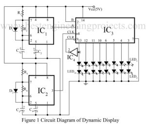
Read MoreDynamic Display Ads Circuit
This project of “Dynamic Display Ads Circuit” is based on serial input and parallel output sift register 74164. With the help of the project dynamic display ads circuit we can build a display board, where LEDs blink to give a running light effect. Circuit Description of Dynamic Display Ads Circuit The project dynamic display ads circuit may be used to advertise or display of name plates etc. It is made versatile by using the 555 and 74 series of ICs, which are readily available in the market. In the dynamic…
Read MoreDigital Clock Circuit with Seconds and Alarm Time Display
Most of the digital clock available on the website is only capable to display hour and minute only. Now, here is a project called Digital Clock Circuit with Second and Alarm Time Display which shows not only hour, minute, and second but also alarm time. Best Engineering Projects (BEP) verify the project Digital Clock with Second and Alarm time display with the help of ten 7-segment displays and clock chip mm5387ANN. Circuit Description of Digital Clock Circuit with Seconds and Alarm Timer Display The entire circuit of the Digital Clock…
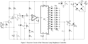
Read MoreUltrasonic Lamp Brightness Controller Circuit
Wireless control of devices using infrared is not new to electronics hobbyists. Now, here is wireless control of the device using ultrasonic sound waves tested in BEP Lab. The project ultrasonic Lamp brightness controller circuit uses ultrasonic sound waves (above 20 kHz) for remote control of lamp brightness. Circuit Description of Ultrasonic Lamp Brightness Controller Circuit As with all wireless control systems, the Ultrasonic lamp-brightness controller comprises a transmitter and receiver circuit. Transmitter Circuit | Ultrasonic Lamp Brightness Controller Circuit The transmitter circuit generates an ultrasonic sound wave of about 40-50…
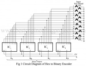
Read MoreHex to Binary Converter Circuit
The circuit described here is a hex to binary converter circuit using four, 8-input NAND gate 7430 ICs. The input keyboard switches SW1 to SW15 are connected in such a manner that the pressing of any switch produces the binary ABCD outputs of the corresponding decoded numbers. When all inputs in a NAND gate are high, it produces a low output, But when any of its input goes low, its output becomes high. Normally, all switches are open, the binary output is 0000. Pressing a switch gives a ‘low input’…
Read MoreProgrammable Digital Timer Circuit
The project “programmable digital timer circuit” presented here can be used for setting time intervals in the range of 1 to 99 minutes. The circuit of a programmable digital timer does not use large resistors or capacitors to obtain the timing interval. Instead, it uses the 50 Hz mains frequency as a reference. The main frequency is fairly accurate for this application. The main frequency is shaped up by Schmitt-trigger gate N1 to obtain a square wave. This 50 Hz square wave is divided by IC1, IC2, IC3, and IC4.…
Read MoreLED Stop Watch Circuit
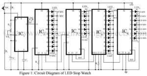
ICs 555 and 4017 are well-known to electronics hobbyists. Presented here is a very interesting project of an LED stopwatch Circuit using timer 555 and decade counter 4017 ICs. This stopwatch is able to monitor time from one second to 60 minutes. It can be used in sports, laboratories, etc. IC 555 (IC1) is the heart of the circuit. It is used in astable multivibrator mode. The special feature of this mode is that if this pin 4 of IC1 is kept at a high logic, it produces a clock…
Read MoreThree Bit flash Analog to Digital Converter Circuit
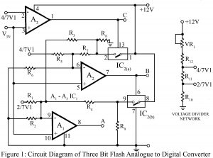
The flash type converter is the simplest and the fastest type of analog to digital converter. The entire digital output word is present just after the propagation delay time of comparators and the encoding logic gates. A typical conversion time of a three-bit flash analog to a digital converter is 33 ns. The circuit of a three-bit flash analog to digital converter shown in figure 1, needs just three comparators and no combinational logic circuitry. Circuit Description of Three Bit Flash Analog to Digital Converter In this circuit, the reference…
Read More
