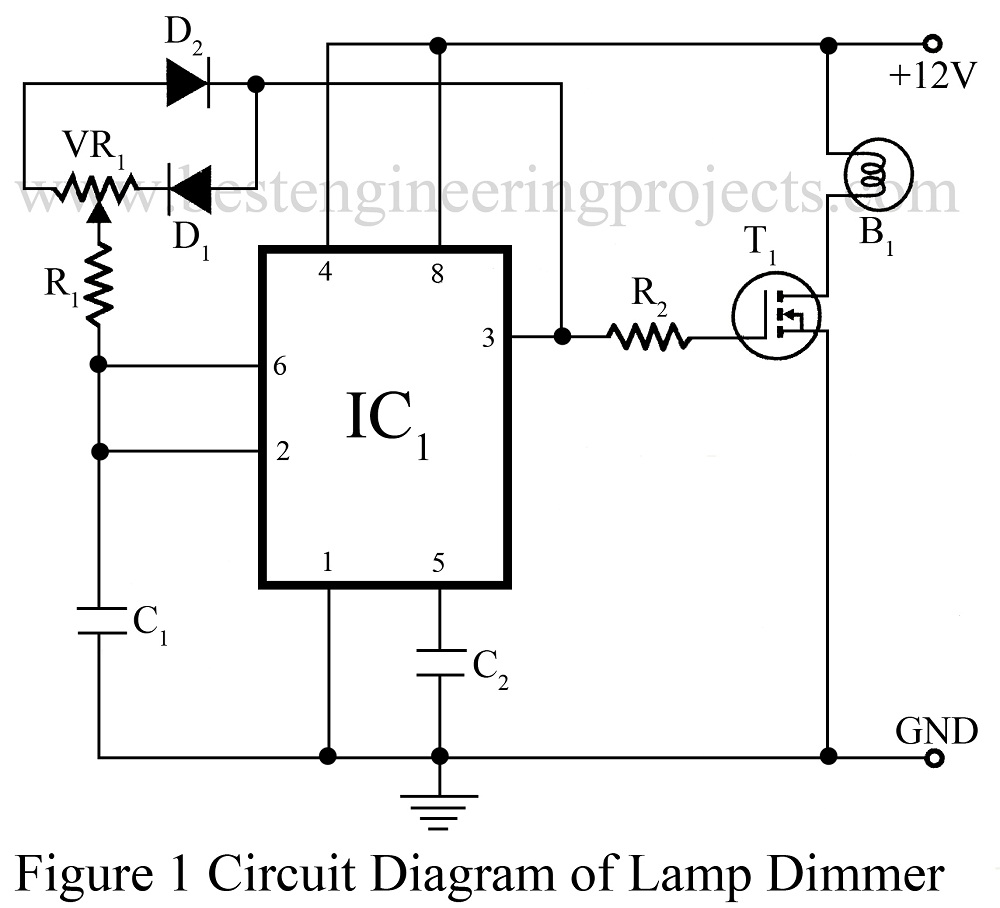
As we have already published various types of lamp dimmer like Light Dimmer Circuit using Capacitor and Touch Dimmer Circuit using triac etc. Now here is a lamp dimmer for the dome lamp in the car, which gives a fairly linear control over the lamp brightness from low to high intensity. The main advantage of the project dome lamp dimmer circuit is it consumes little power because it is a pulse-width modulated chopper circuit. You can also control the intensity of a halogen bulb or control the speed of a mini drill by using the circuit.
Description of Dome Lamp Dimmer Circuit
The circuit of the dome lamp dimmer is built around timer IC NE555 (IC1), and a MOSFET. IC1 is used as an astable multivibrator to produce a square wave. Capacitor C1 is charged and discharged from the output of IC1 via diode D1 and D2. Adjust potmeter VR1 to control the RC time constant during the charge-discharge cycle and get the timer output with the desired pulse width. In this way, the brightness of the lamp can be varied from low to high by adjusting potmeter VR1. Use a suitable heat sink for the MOSFET T1 to handle the load current.

BEP NOTE: As we know that most cars run only one wire to power the lamp and use the car body to return the current path. Connect the ground path of the circuit to the car body.
PARTS LIST OF DOME LAMP DIMMER CIRCUIT
|
Resistor (all ¼-watt, ± 5% Carbon) |
|
R1 = 1 KΩ R2 = 47 KΩ VR1 = 22KΩ POT |
|
Capacitors |
|
C1, C2 = 0.01 µF (Ceramic Disc) |
|
Semiconductors |
|
IC1 = NE555 (Timer IC) D1, D2 = 1N4148 (Small Signal Diode) T1 = IRF540 (N-Channel MOSFET) |
|
Miscellaneous |
|
B1 = 12V bulb |