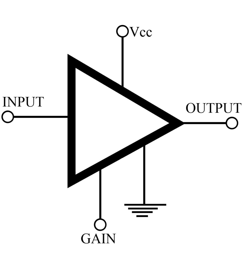
In Class A amplifier the input signal is reproduced, increased in amplitude, in exactly the same wave shapes at the output. To achieve this, the quiescent point (Q) is at the center of the collector current (IC) curve, so that the input signal as well as the amplitude output signal operates only over the linear portion of this curve. IC flows at all times. Class A amplifiers are used whenever the output wave shape must be the same, with a minimum of distortion, as the input signal. Operational amplifiers, and “small signal” amplifiers. Such as RF, IF, preamplifiers, etc., are all basically Class A amplifiers.
Key Parameters of Class A Amplifier
- Gain: Depending on the application and type of amplifier, this may be expressed as voltage gain, current gain or power gain, usually in dB. In may types of amplifier the gain can be electronically controlled by varying DC signals, such as the automatic gain control (AGC), in a receiver. Manual gain control gain be applied through a potentiometer connected to the gain terminal on the amplifier.
- Frequency (bandwidth): Class A amplifiers generally do not have a lower frequency limit, but the upper limit, together with the maximum gain possible at the upper frequency, is an important parameter. This frequency limit is independent of external resonant networks and frequency compensating networks.
- Linearity distortion: This parameter is usually given as the maximum peak-to-peak input signal voltage. In audio circuit applications the percent of output signal distortion, under specific operating conditions, is sometimes stated in the specifications.
- Power Output: The maximum power output is stated either as dB with a given input or as the maximum peak-to-peak voltage across a specified load impedance.
- Noise: Stated as signal-to-noise ratio or simply as noise figure, this parameter indicates the amount of noise generated within the amplifier with a specified input impedance.
- Power dissipation: The maximum power dissipation, in milli watts or watts, not only indicates the power required from the supply but is also a measure of the temperature rise and, if necessary, of the heat sink requirements of the particular amplifier.
Applications of Class A Amplifier
Class A amplifiers are used as low-level amplifier in audio circuits, in the RF and IF stages of receivers of all kinds, and in the video stages of TV receivers and displays. Basic Class A amplifiers can also be connected as operational amplifiers, servo amplifiers, power amplifiers, instrumentation amplifiers, and in any other application where the input signal is amplified in a linear fashion. When used as RF and IF amplifiers the input and output circuits are generally resonant circuits tuned to a selected band of frequencies. It is essential in these applications that the frequency or bandwidth characteristics of the IC itself go beyond the frequency band they must amplify. In the case of video amplifiers, low frequency compensating networks may be necessary to boost the low frequency components of the video signal that may have been reduced in other parts of the system.
Parts Number: Analog Device AD101A
Comments
Some ICs may be labeled by their specific applications, such as audio and video amplifiers, but they can be used for other purposes, such as instrumentation amplifiers, as long as the key parameters listed above are suitable. In some instance, Class A amplifiers can be changed to Class AB, B, or even C operated by changing the bias level.
