Automatic and Manual Temperature Control unit: Automation have reached almost everywhere whether it is home automation or agriculture field. Automation system collect different parameter such as temperature, humidity etc. in real time basis and keep control of fan, moist control etc. But sometime we need manual control over various actuator or load like motor, fan etc. wither testing of load or when automatic system does not work. This project is the modified version of Arduino Based Temperature Controlled Fan.
Manual mode is also considered as backup mode with which we can control load manually according to our requirement. So, in this project we will learn about automation and as well as manual control system so that one can control load in both automatic and manual mode. For demo we are consider temperature control unit. In this project we will control fan in automatic mode and in manual mode.
Circuit Description of Arduino Based Automatic and Manual Temperature Control unit
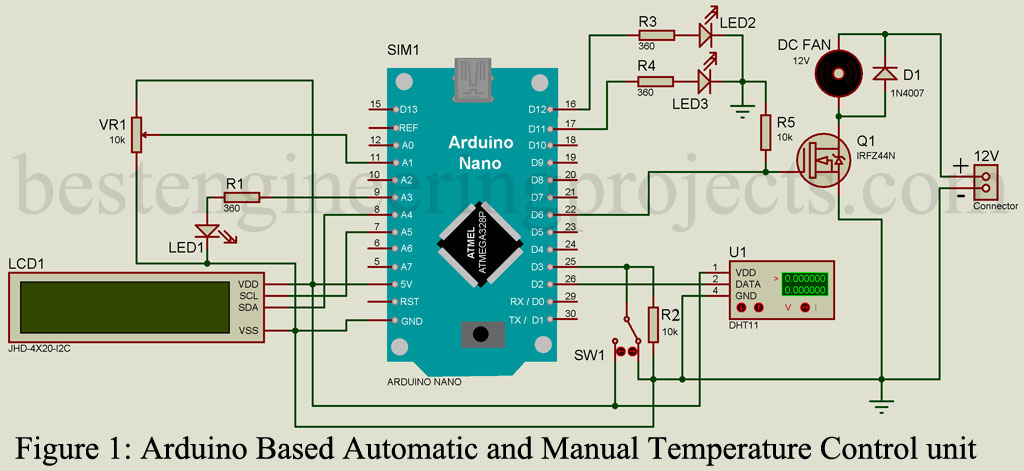
The circuit is built around arduino nano, DHT11 (temperature and humidity sensor), a 20×4 I2C LCD, Z44N (MOSFET) and few other components like resistor, led, switch etc.
Component Required
1x Arduino Nano
1x DHT11
1x 20×4 I2C LCD
1 x Z44N
1x SPDT Switch
3x 5mm LED (Any color)
1x 1N4007
3x 360-ohm Resistor
2x 10k-ohm Resistor
1x 10k-ohm POT.
1x 12V DC Fan
1x 12V Power Supply
DHT11 Sensor is used to sense the temperature and humidity. A DPST Switch SW1 is used to select the mode of operation i.e. Automatic mode and Manual Mode. A 20×4 I2C LCD is used to display data like temperature, humidity, mode of operation and fan speed. A potentiometer VR1 is sued to adjust the speed of fan in manual mode. A switching circuit is designed around a N-Channel MOSFET IRFZ44N. We are using PWM pin instead of normal digital pin, because MOSFET is voltage control device i.e. voltage at gate (G) determine the conduction level. PWM pin can supply different voltage from the range of 0V to 5V in 255 steps. This is required for variable fan speed. Check out another project based on DHT11, “Temperature, Humidity and Heat Index Meter using Arduino“.
A resistor of 10K is connected between ground and gate in order to avoid false triggering of MOSFET. Source pin (S) of MOSFET is grounded where drain pin of MOSFET is connected to negative terminal of fan. Positive terminal of fan is connected +12V power supply. A diode D1 is connected across fan in order to protect form reverse fly-back voltage. Glowing LED1, LED2, LED3 indicates Max. Temperature, Automatic Mode and Manual Mode respectively.
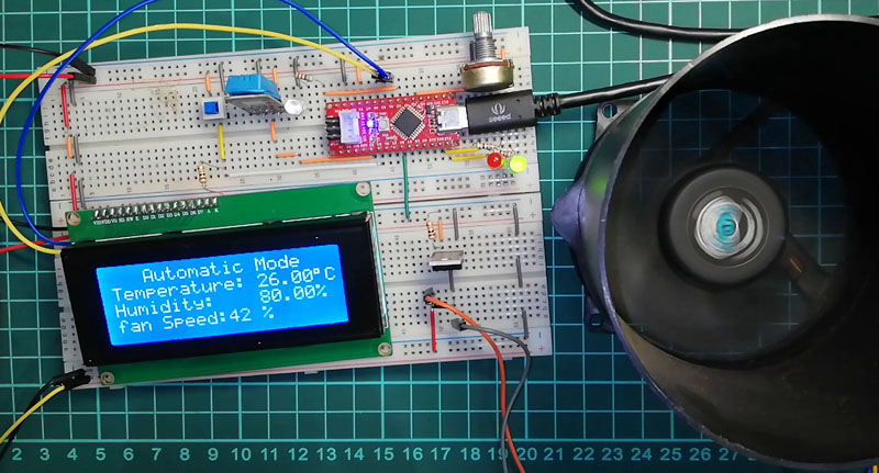
Figure 2: Author Prototype of Arduino Based Automatic and Manual Temperature Control unit
Software Code: Software code is written is arduino programming language and compiled in arduino programming. Let’s see the code Breakdown.
Automatic Mode:
|
1 2 3 4 5 6 7 8 9 10 11 12 13 14 15 16 17 18 19 20 21 22 23 24 25 26 27 28 29 30 31 32 33 34 35 36 37 38 39 40 41 42 43 44 45 46 47 |
//Auto Mode Start if(CheckButton == HIGH){ digitalWrite(ManLed, LOW); digitalWrite(AutoLed, HIGH); lcd.setCursor(0,0); lcd.print(" "); lcd.setCursor(0,0); lcd.print(" Automatic Mode"); if(Temp < tempMin) { lcd.setCursor(0,3); lcd.print(" "); fanSpeed = 0; analogWrite(fan, fanSpeed); fanLCD=0; lcd.setCursor(0,3); lcd.print("Min Temp (Fan OFF)"); } if((Temp >= tempMin) && (Temp <= tempMax)) { lcd.setCursor(0,3); lcd.print(" "); fanSpeed =map(Temp, tempMin, tempMax, 32, 255); fanLCD = map(Temp, tempMin, tempMax, 0, 100); // speed of fan to display on LCD100 analogWrite(fan, fanSpeed); // spin the fan at the fanSpeed speed lcd.setCursor(0,3); lcd.print("fan Speed:"); lcd.setCursor(10,3); lcd.print(fanLCD); lcd.setCursor(13,3); lcd.print("%"); } if(Temp > tempMax) { analogWrite(fan, 255); // spin the fan at the fanSpeed speed lcd.setCursor(0,3); lcd.print(" "); digitalWrite(maxLed, HIGH); lcd.setCursor(0,3); lcd.print("Max Temp.(Max Speed)"); } else { digitalWrite(maxLed, LOW); } } //Auto Mode End |
Temperature sensor detect temperature and operate fan at speed of corresponding temperature. In this demo project minimum temperature is set to 200C and maximum temperature set to 300C. In this mode we will operate fan with three different condition.
- When Temperature is less then minimum temperature: Fan will be turned off with message of “Min Temp (Fan OFF)”.
- When temperature is between minimum temperature and maximum temperature: Fan Spin at the speed of corresponding temperature. Here, difference of maximum temperature and minimum temperature is map between 1% to 100% speed.
Let’s say Minimum temperature = 230C
Maximum TEMPERATURE = 300C
Temperature difference = Max. temp – Min temp. = 30 – 23 = 70C
At 230C, Fan spin at 0% similarly at 300C fan spin at 100%.
Map = 100/7 = 14.28 = 14%. So, per degree increase in temperature increase the speed of fan by 14%.
When Temperature is more the maximum temperature: Far will spin at full speed (100%) with message “Max Temp(Max Speed)”. Maximum Temperature is also indicate by glowing LED3.
Automatic mode is indicated by message on display “Automatic Mode” and glowing LED1 indicate.
Manual Mode:
|
1 2 3 4 5 6 7 8 9 10 11 12 13 14 15 16 17 18 19 20 21 22 |
//Manual Mode Start if(CheckButton == LOW){ digitalWrite(ManLed, HIGH); digitalWrite(AutoLed, LOW); lcd.setCursor(0,0); lcd.print(" "); lcd.setCursor(10,3); lcd.print(" "); lcd.setCursor(0,0); lcd.print(" Manual Mode "); int vout = analogRead(ManSpeed); fanManSpeed = map(vout, 0, 1023, 0, 255); fanManLCD = map(vout, 0, 1023, 0, 100); analogWrite(fan, fanManSpeed); // spin the fan at the fanSpeed speed lcd.setCursor(0,3); lcd.print("Fan Speed:"); lcd.setCursor(10,3); lcd.print(fanManLCD); lcd.setCursor(13,3); lcd.print("%"); } //manual Mode End |
In this mode sped of fan is not affected by temperature any more. Speed of fan is manually adjusted by POT (VR1). In this mode speed of fan is corresponding to output voltage from VR1. Manual mode is indicated by message on display “Manual Mode” and glowing LED2 indicate.
At 0V, Fan spin at 0% similarly at 5V fan spin at 100%.
Map = 100/5 = 20%. So, per voltage speed of fan increase 20%.
Complete Source Code
|
1 2 3 4 5 6 7 8 9 10 11 12 13 14 15 16 17 18 19 20 21 22 23 24 25 26 27 28 29 30 31 32 33 34 35 36 37 38 39 40 41 42 43 44 45 46 47 48 49 50 51 52 53 54 55 56 57 58 59 60 61 62 63 64 65 66 67 68 69 70 71 72 73 74 75 76 77 78 79 80 81 82 83 84 85 86 87 88 89 90 91 92 93 94 95 96 97 98 99 100 101 102 103 104 105 106 107 108 109 110 111 112 113 114 115 116 117 118 119 120 |
#include <DHT.h> #include <LiquidCrystal_I2C.h> //Library for I2C lcd LiquidCrystal_I2C lcd(0x27,20,4); #define DHTPIN 2 #define DHTTYPE DHT11 DHT dht(DHTPIN, DHTTYPE); int AutManMode = 3; int ManSpeed = A1; int maxLed = A3; int fan = 6; float tempMin = 23.0; float tempMax = 30.0; int AutoLed = 12; int ManLed = 11; int fanSpeed, fanLCD, fanManSpeed,fanManLCD; void setup() { lcd.init(); //initialization the lcd lcd.backlight(); dht.begin(); pinMode(AutManMode, INPUT); pinMode(ManSpeed, INPUT); pinMode(fan, OUTPUT); pinMode(maxLed, OUTPUT); pinMode(AutoLed, OUTPUT); pinMode(ManLed, OUTPUT); } void loop(){ float RH = dht.readHumidity(); float Temp = dht.readTemperature(); lcd.setCursor(0,1); lcd.print("Temperature:"); lcd.setCursor(13, 1); lcd.print(Temp); lcd.setCursor(18,1); lcd.write(B11011111); lcd.setCursor(19,1); lcd.print("C"); lcd.setCursor(0,2); lcd.print("Humidity:"); lcd.setCursor(13,2); lcd.print(RH); lcd.setCursor(18,2); lcd.print("%"); int CheckButton = digitalRead(AutManMode); //Auto Mode Start if(CheckButton == HIGH){ digitalWrite(ManLed, LOW); digitalWrite(AutoLed, HIGH); lcd.setCursor(0,0); lcd.print(" "); lcd.setCursor(0,0); lcd.print(" Automatic Mode"); if(Temp < tempMin) { lcd.setCursor(0,3); lcd.print(" "); fanSpeed = 0; analogWrite(fan, fanSpeed); fanLCD=0; lcd.setCursor(0,3); lcd.print("Min Temp (Fan OFF)"); } if((Temp >= tempMin) && (Temp <= tempMax)) { lcd.setCursor(0,3); lcd.print(" "); fanSpeed =map(Temp, tempMin, tempMax, 32, 255); fanLCD = map(Temp, tempMin, tempMax, 0, 100); // speed of fan to display on LCD100 analogWrite(fan, fanSpeed); // spin the fan at the fanSpeed speed lcd.setCursor(0,3); lcd.print("fan Speed:"); lcd.setCursor(10,3); lcd.print(fanLCD); lcd.setCursor(13,3); lcd.print("%"); } if(Temp > tempMax) { analogWrite(fan, 255); // spin the fan at the fanSpeed speed lcd.setCursor(0,3); lcd.print(" "); digitalWrite(maxLed, HIGH); lcd.setCursor(0,3); lcd.print("Max Temp.(Max Speed)"); } else { digitalWrite(maxLed, LOW); } } //Auto Mode End //Manual Mode Start if(CheckButton == LOW){ digitalWrite(ManLed, HIGH); digitalWrite(AutoLed, LOW); lcd.setCursor(0,0); lcd.print(" "); lcd.setCursor(10,3); lcd.print(" "); lcd.setCursor(0,0); lcd.print(" Manual Mode "); int vout = analogRead(ManSpeed); fanManSpeed = map(vout, 0, 1023, 0, 255); fanManLCD = map(vout, 0, 1023, 0, 100); analogWrite(fan, fanManSpeed); // spin the fan at the fanSpeed speed lcd.setCursor(0,3); lcd.print("Fan Speed:"); lcd.setCursor(10,3); lcd.print(fanManLCD); lcd.setCursor(13,3); lcd.print("%"); } //manual Mode End delay(1000); } |

