This article shows you how to make caller ID for two wheeler’s i.e. bike or scooter. This caller ID display cell phone number when any one call you or when you call anyone while riding bike or scooter. Sometime It is difficult to identify the caller while riding two-wheeler vehicles because usually we keep our mobile either in pocket or in bag. Sometime even we get confused whether the vibration is of vehicle or of mobile. By using this simple device one can know about caller and can easily distinguished between vehicle engine vibration and mobile vibration.
Components Required Arduino Based Caller ID for Bike
Arduino Nano x 1
16×2 LCD x 1
HC-06 Bluetooth Module x 1
10K Variable resistor x 1
330-ohm Resistor x 1
Circuit Description of Arduino Based Caller ID for Bike
Circuit diagram is shown in figure 1 and is built around Arduino Nano, 16×2 LCD and HC-06 Bluetooth module.
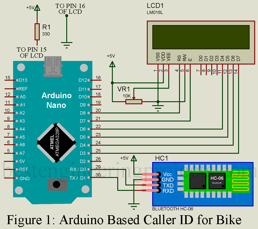
Power supply pin (Vcc and GND) of Bluetooth module is connected to +5V and GND pin of arduino respectively. Communication between Bluetooth module and Arduino Nano is of serial type thus, transmitter pin of module is connected to receiver pin of arduino and receiver pin of module is connected to transmitter pin of arduino as shown in circuit diagram.
Alphanumeric LCD 16×2 is connected in higher order data mode i.e. Data pin D4 to D7 is used here for display message on LCD. LCD pin 1 (Vss), pin 5 (RW) and pin 16 (LED-) is connected to ground (GND) of arduino. LCD pin 2 (VDD) is connected to +5V power supply. Pin 3 of LCD (VEE) is responsible for contrast control and voltage level at this pin must be between voltage at VDD and VSS pin of LCD. For contrast control we are using a variable resistor where two fix pins are connected to +5V and GND pin as shown in circuit diagram and wiper is connected to pin 3 (VDD) of LCD. Pin 4 (RS) and Pin 6 (EN) of LCD is connected to arduino Nano D8 and D7 pin respectively. Four higher order data pins of LCD (D4, D5, D6 and D7) is connected to arduino Nano D6, D5, D4 and D3 pin respectively as shown in circuit diagram. Pin 15 of LCD is connected to +5V through a current limiting resistor R1 of 330-ohms.
If you have any confusion while interfacing LCD please watch the making video of Tutorial on Interfacing of 16×2 LCD using Arduino
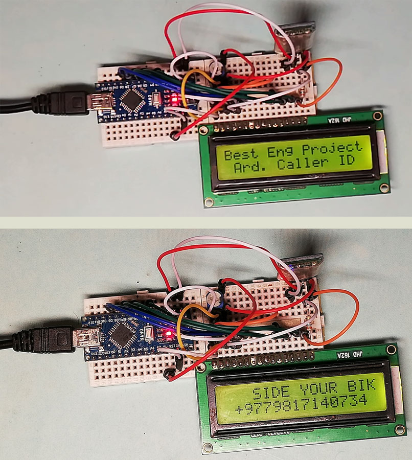 Figure 2: Author Prototype of Arduino Based Caller ID for Bike
Software: The software code for Arduino Based Caller ID for Bike is written in arduino programming language and compiled using Arduino IDE. Software code is very simple, this arduino detect the message coming from mobile and display over LCD.
|
1 2 3 4 5 6 7 8 9 10 11 12 13 14 15 16 17 18 19 20 21 22 23 24 25 26 27 28 29 30 31 32 33 34 35 36 37 38 39 40 41 42 43 44 45 |
#include<LiquidCrystal.h> //Library for LCD LiquidCrystal lcd(8, 7, 6, 5, 4, 3); //difining LCD pin String inData;//defining variable with String type //Setup Function start here void setup() { Serial.begin(9600);//communication speed i.e. 9600 bps lcd.begin(16, 2); lcd.print("Best Eng Project");//printing initail message lcd.setCursor(1,1);//Set cursor to second row lcd.print("Ard. Caller ID"); delay(3000);//Ste delay for 3 seconds lcd.clear();//Clear the LCD } //Loop Function start here void loop() { int i=0; char commandbuffer[100]; //check whether serial is available or not if(Serial.available()) { lcd.clear(); delay(100); //add the value of serial data to commandbuffer array while(Serial.available() && i<99) { commandbuffer[i++] = Serial.read(); } commandbuffer[i++]='\0'; } if(i>0) { Serial.println((char*)commandbuffer); //Print Message over LCD lcd.setCursor(1,1); lcd.print((char*)commandbuffer); } delay(1000); } |
Note: While uploading program to your arduino Nano from computer please remove the connection of Bluetooth i.e. disconnect the Tx and RX of Bluetooth from arduino Nano.
You may also like other interesting Arduino based projects posted in bestenginerringprojects.com
- Appliance control using IOT and AI Chatbot
- Accident Detection and Alert System using Arduino
- Car Lock System using Arduino and GSM
Android application is developed using MIT App inventor, you can directly download the apk file from the link below and use on your mobile.
Click here to download the android application
Working of the circuit
- Start the bike (it will switch on the circuit), pair Bluetooth module with your mobile.
- Open application “Arduino Caller ID” and then click on Connect.
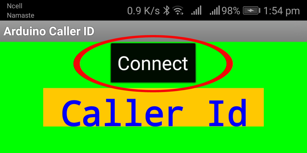
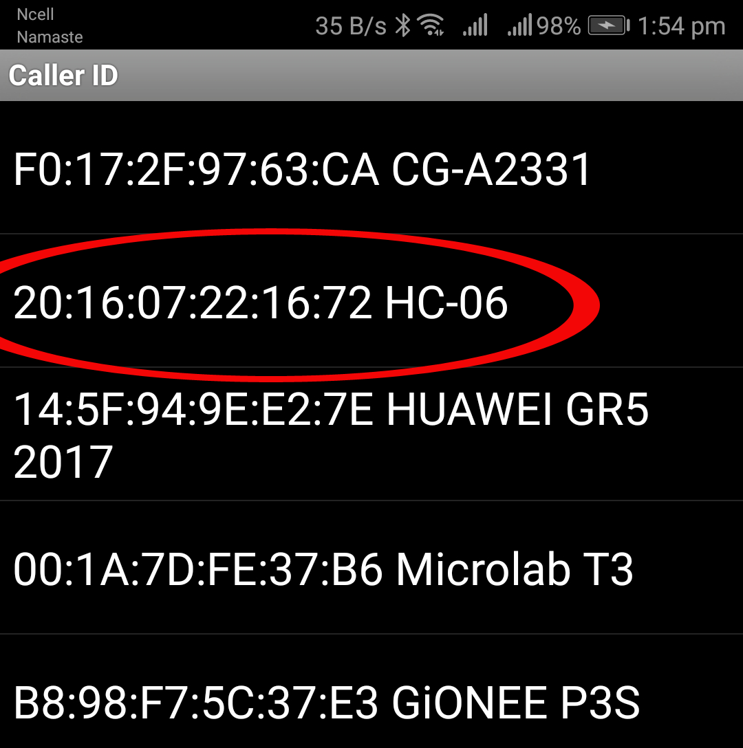
- Click on HC-06, if every thing will be ok then this app connects with Bluetooth module.
- When any one call you the number of callers will display on LCD.
Note: Don’t kill the app i.e. app must run in background. You can minimize this app.