Waveguide Termination: Since a waveguide is a single conductor, it is not as easy to define its characteristic impedance (Z0) as it is for a coaxial line. Nevertheless, you can think of the characteristic impedance of a waveguide as being approximately equal to the ratio of the strength of the electric field to the strength of the magnetic field for energy traveling in one direction. This ratio is equivalent to the voltage-to-current ratio in coaxial lines on which there are no standing waves. For an air-filled rectangular waveguide operating in the dominant mode, its characteristic impedance is given by
….(1)
where E is the characteristic impedance of free space = 120 = 377
. The guide’s characteristic impedance is affected by the frequency of the energy in it since
. Therefore, the guide’s impedance is variable and more correctly termed characteristic wave impedance rather than just characteristic impedance.
Waveguide Termination
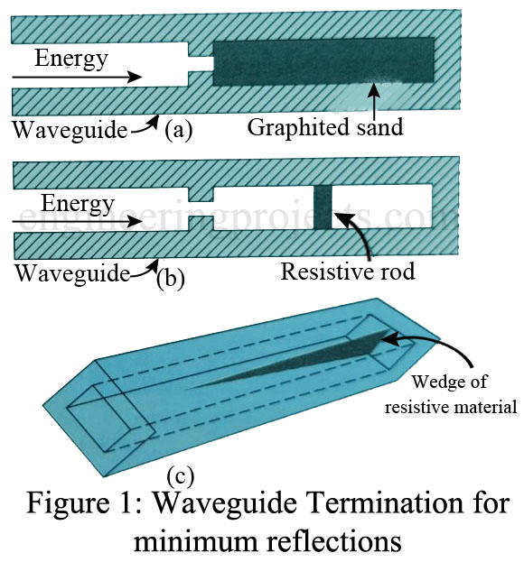
On a waveguide, there is no place to connect a fixed resistor to terminate it in its characteristic (wave) impedance as there is on a coaxial cable. But there are a number of special arrangements that accomplish the same result. One consists of filling the end of the waveguide with graphited sand, as shown in Figure 1(a). As the fields enter the sand, currents flow in it. These currents create heat, which dissipates the energy. None of the energy dissipated as heat is reflected back into the guide. Another arrangement [Figure 1(b)] uses a high-resistance rod, which is placed at the center of the E field. The E field (voltage) causes current to flow through the rod. The high resistance of the rod dissipates the energy as an I2R loss.
Still another method for waveguide termination is to use a wedge of resistive material [Figure 1(c)]. The plane of the wedge is placed perpendicular to the magnetic lines of force. When the H lines cut the wedge, a voltage is induced in it. The current produced by the induced voltage flowing through the high resistance of the wedge creates an I2R loss. This loss is dissipated in the form of heat. This permits very little energy to reach the closed end to be reflected.
Each of the preceding waveguide terminations is designed to match the impedance of the guide in order to ensure a minimum of reflection. On the other hand, there are many instances where it is desirable for all the energy to be reflected from the end of the waveguide. The best way to accomplish this is to simply attach or weld a metal plate at the end of the waveguide.
Variable Attenuators
Variable attenuators find many uses at microwave frequencies. They are used to
- isolate a source from reflections at its load so as to preclude frequency pulling
- adjust the signal level, as in one arm of a microwave bridge circuit, and
- measure signal levels, as with a calibrated attenuator:
There are two versions of variable attenuators:
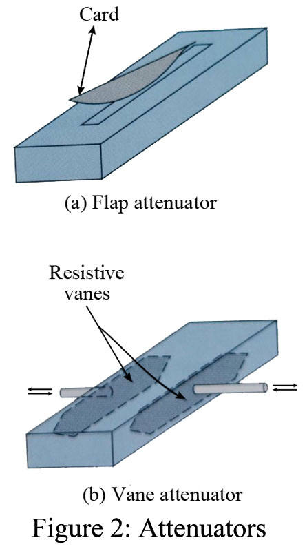
- Flap attenuator [Figure 2(a)]: Attenuation is accomplished by the insertion of a thin card of resistive material (often referred to as a vane) through a slot in the top of the guide. The amount of insertion is variable, and the attenuation can be made approximately linear with insertion by proper shaping of the resistance card. Notice the tapered edges, which minimize unwanted reflections.
- Vane attenuator [Figure 2(b)]: In this type of attenuator the resistance card or vanes move in from the sides, as shown in the figure. It can be seen that the losses (and thus attenuation) will be minimum when the vanes are close to the side walls where E is small and maximum when the vanes are in the center.

