In this article, we will learn about strobed buffer or Inverter IC CD4502, its parameter, truth table and its application.
Description of Strobed Buffer or Inverter IC
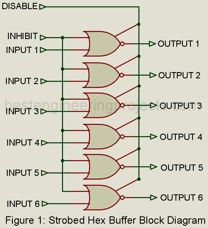
This IC provides the basic buffer or inverter function as well as two additional control functions. As illustrated in figure 1, all six inputs are controlled by a single “inhibit” signal, and all six outputs are controlled by a single “disable” signal. This permits each of the six inputs and outputs to have a total of three possible states, as indicated by the truth table of table 1.
Because this is an inverting buffer, when the input is 0 and both the inhibit and disable signals are 0, the output will be 1. When the input is 1, the output will be 0 if both the inhibit and disable signals remains 0. In short, with inhibit and disable signals at 0, the circuit acts as a simple hex inverter or buffer. When the inhibit signal is 1, the output will be 0 regardless of what the input signal will be. If the disable signal is 1, the output will represent a high impedance regardless of what the input or the inhibit signals will be.
Check out article on Buffer or Inverter IC
Key parameters
The electrical characteristics of this IC will be the same as those of the particular digital IC family.
- Propagation delay time: The time delay between input and output of any terminal. 200 ns is typical for CMOS devices.
- Minimum disable setup time: The minimum time it takes from the application from the disable signal until all six buffer or inverters are disabled. 20 to 50 ns is typical for CMOS.
- Minimum hold time for disable signal: The minimum time required for the disable signal to remain on in order for data to be disabled. 25 to 75 ns is typical for CMOS devices.
Applications
This IC is useful as 3-state hex inverter for interfacing other ICs with data buses. Other controlled interface applications are also possible.
Representative Part Number: RCA CD4502
| Table 1: Truth Table | |||
| INPUT | INHIBT | DISABLE | OUTPUT |
| 0 | 0 | 0 | 1 |
| 1 | 0 | 0 | 0 |
| X | 1 | 0 | 0 |
| X | X | 1 | HIZ |
Where X – Value Immaterial
