Light offers the fastest path for transmission of signals in comparison to any other medium. The circuit “Speech Communication using Laser” makes use of this aspect, it is a one or two-way optical communications system using a short-wavelength visible laser diode (say, RLT6505 or the laser module of a laser pointer) as the light-emitting element, free space as the transmission media and a light-dependent resistor as the light-receiving element. This system is a perfect medium for speech communication between two adjacent offices or between homes on the opposite sides of a road.
System description of Speech Communication Using Laser
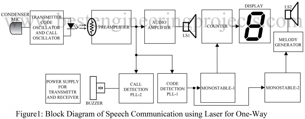
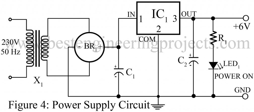
The project “Speech Communication using Laser” can be used as both; one-way or two-way communication with slight modifications in the circuit. The block diagram of the Speech Communication using Laser for one-way speech communication is shown in fig. 1. It comprises a transmitter, receiver, and a common DC power supply section. The power supply section, at one end of the link, provides regulated 6V to the receiver-transmitter circuit. For two-way communication, you need to use an identical system, with the positions of the receiver and the transmitter reversed, with this system.
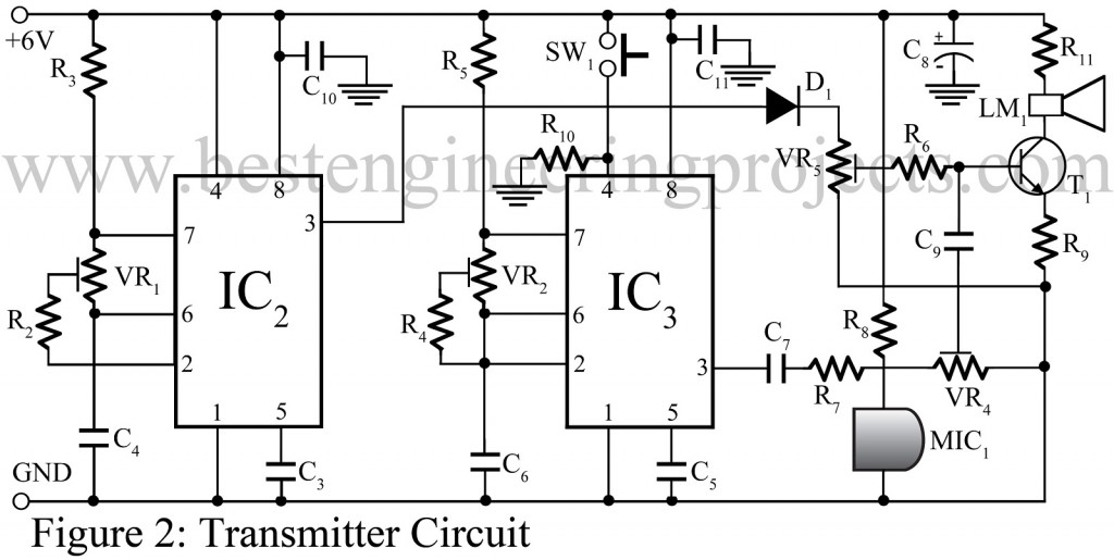
Transmitter Circuit | Speech Communication using Laser
In the transmitter section, the intensity of the laser beam is modulated by the output of an always-on code oscillator (operating at 10-15 kHz). Using a push to-on switch, the tone oscillator (operating at 1-2 kHz) is momentarily activated to alert the person at the receiver end before starting a voice communication using the microphone.
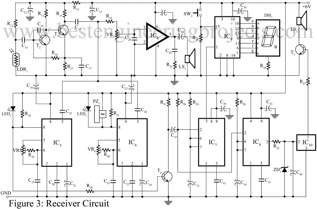
Receiver Circuit | Speech Communication using Laser
The receiver receives the intensity-modulated light signals through a light sensor and outputs the code and 1kHz tone/voice.
The circuit for detecting the code signal is built around a phase-locked loop (PLL-1). The absence of the code signal indicates interception of the laser beam and activates an audio-visual warning at the remote receiver. For detecting the 1kHz call/tone signal, another phase-locked loop (PLL-2) is used. The call detection is indicated by a buzzer sound and an LED.
Check out more other interesting projects using Laser, posted on bestengineeringprojects.com
- Laser-Based Communication Link
- Mini Laser Turret
- LASER Demonstration Program using C
- Laser Voice Transmitter Circuit
PARTS LIST OF SPEECH COMMUNICATION USING LASER
| Resistors (all ¼-watt, ± 5% Carbon unless stated otherwise) |
| R1, R19, R20, R27, R32 = 1 KΩ
R2 – R5 = 5.6 KΩ R6, R8, R18, R21, R28 = 8.2 KΩ R7, R12 = 15 KΩ R9 = 22 Ω R10 = 2 KΩ R11 = 68 Ω R13, R17, R26 = 2.2 KΩ R14 = 2.7 KΩ R15 = 390 Ω R16 = 390 KΩ R22 = 33 KΩ R23 = 4.7 Ω R24 = 36 KΩ R25 = 560 KΩ R29 = 4.7 KΩ R30 = 220 Ω R31 = 10 KΩ VR1 = 47 KΩ Preset VR2 = 100 KΩ Preset VR 3 = 10 KΩ Potmeter VR4 = 5 KΩ Preset VR5, VR6 = 10 KΩ Preset VR7 = 100 KΩ Potmeter (LOG.) |
| Capacitors |
| C1 = 2200 µF, 25V (Electrolytic Capacitor)
C2, C12, C13, C40 = 100 µF, 16V (Electrolytic Capacitor) C3, C5, C6, C9, C19, C22, C32, C35 = 0.01 µF (Ceramic Disc) C4 = 3.3 nF (Ceramic Disc) C7, C10, C11, C14, C15, C17, C20, C26, C29 = 0.1 µF (Ceramic Disc) C8, C36, C38 = 470 µF, 16V (Electrolytic Capacitor) C16 = 56 pF (Ceramic Disc) C18, C27, C33, C39 = 10 µF, 16V (Electrolytic Capacitor) C21, C24 = 2.2 µF, 16V (Electrolytic Capacitor) C23, C28 = 0.22 µF (Ceramic Disc) C25 = 1 nF (Ceramic Disc) C30 = 47 µF, 16V (Electrolytic Capacitor) C31 = 1 µF, 16V (Electrolytic Capacitor) C34 = 6.8 µF, 16V (Electrolytic Capacitor) C37 = 3.3 µF, 16V (Electrolytic Capacitor) |
| Semiconductors |
| IC1 = 7806, (6V Series Voltage Regulator IC
IC2, IC3, IC7, IC8 = NE555 (Timer IC) IC4 = LM386 (Low power audio amplifier) IC5, IC6 = NE567 (Phase-locked loop) IC9 = CD4033 (Decade Counter/7-segment Decoder) IC10 = UM66 (Melody generator) BR1 = 1A Bridge rectifier D1 = 1N4001 (Rectifier diode) ZD1 = 3.3 V Zener diode LED1 – LED3 = 5mm red LED DIS1 = LTS543 (Common-cathode display) |
| Miscellaneous |
| SW1, SW2 = Push-to-on tactile switch
LS1, LS2 = 8-Ω 1W speakers MIC1 = Condenser microphone PZ1 =Piezo buzzer X1 = 230V AC primary to 0-9V, 500mA secondary transformer Laser Module |


Hi sir! how to make the drone.