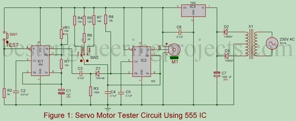
I believe testing circuits are a must for project geeks since these testers save so much time in debugging circuits. People invest all their efforts and spend so much time completing one project but most of the time they don’t get the desired output. There can be multiple reasons behind this and generally, it is because the components like servo motors are at fault. The project Servo Motor Tester Circuit Using 555 IC was used in the project after isolating it from the project and helping us to detect if the problem lies in the motor or the circuit logic.
Circuit Description and Working of Servo Motor Tester Circuit Using 555 IC
The Servo Motor Tester Circuit Using 555 IC passes pulses of varying width to the motor attached with the circuit and then monitors the output of the motor and evaluates the angle to which it turns concerning the input fed to the motor. For instance, if we supply a 1.5 ms pulse input to the motor, it should turn to a neutral position i.e. 90-degree position.
To avoid any chances of failure, the project Servo Motor Tester Circuit Uses 555 IC feds pulses of varying widths to the motor. The circuit uses two NE555 timer ICs; IC1 and IC2 along with a few other discrete components to generate width varying input pulses. IC1 is used as an astable multivibrator and has a period of 20 ms. This IC also triggers IC2 at the end of 20 ms. It does so by generating a sharp negative pulse. Similarly, IC2 is employed as a monostable multivibrator that produces pulses of different duration; 1 ms, 1.5 ms, and 2 ms to feed the servo motor and monitor its output accordingly.

Pull-down resistor R2 is connected at pin 4 of IC1. Switch S1 and S2 are also included in the circuit. As the switch S1 is closed, the astable multivibrator (IC1) triggers the second IC i.e. IC2 to generate a pulse corresponding to the position of the switch S2 in the circuit. As shown in the circuit diagram, switch S2 can be used to connect any resistors R4, R5, and R6 or all of them, and R7 to develop monostable output pulse of different intervals: 1ms, 1.5 ms, or 2 ms respectively. The period of IC1 is fixed at 20 ms by a preset VR1.
Once the circuit is assembled, select the appropriate resistor and choose the monostable input as 1ms, 1.5 ms, or 2 ms. After that close the switch S1. In doing so, the servo motor must rotate either to the extreme left, middle, or extreme right direction as per the input fed from the circuit to the motor.
Check out other various testing circuits posted on bestengineeringprojects.com
- Speaker Polarity Test Circuit
- RJ45 Cable Tester Circuit
- Zener Diode Tester Circuit
- Relay Tester Circuit
- 5 State Digital IC and Circuit Tester
PARTS LIST OF SERVO MOTOR TESTER CIRCUIT USING 555 IC
| Resistor (all ¼-watt, ± 5% Carbon) |
| R1, R5 = 12 KΩ
R2 = 5 KΩ R3 = 100 KΩ R4, R8 = 10 KΩ R6 = 2 KΩ R7 = 18 KΩ VR1 = 10 KΩ |
| Capacitors |
| C1 = 1 µF, 16V (Electrolytic Capacitor)
C2 = 0.01 nF (Ceramic Disc) C3 – C6 = 0.1 µF (Ceramic Disc) C7 = 1000 µF, 25V (Electrolytic Capacitor) |
| Semiconductors |
| IC1, IC2 = NE555 (Timer IC)
IC3 = LM7805 (5 volt fixed Series Voltage regulator) D1 = 1N4148 (Signal Diode) D2, D3 = 1N4007 (Rectifier Diode) |
| Miscellaneous |
| X1 = 230V AC Primary to 6V – 0 – 6V, 500Ma Secondary Transformer
SW1 = PUSH-TO-ON Switch SW2 = Three-Way Rotary Switch M1 = Servo Motor |
Hi? Can you suggest a project that is using an op-amp, 555, and flipflop? It will be a great help :)