For a wave to exist in a waveguide, it must satisfy Maxwell’s equations throughout the waveguide. These mathematically complex equations are beyond the scope of this article, but one boundary condition of these equations can be put into plain language: There can be no tangential component of the electric field at the walls of the waveguide. This makes sense because the conductor would then short out the E field. An exact solution for the field existing within a waveguide is a relatively complicated mathematical expression. It is possible, however, to obtain an understanding of many of the properties of waveguide propagation from a simple physical picture of the mechanisms involved.
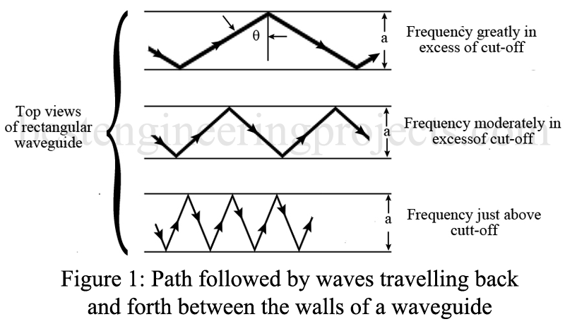
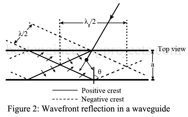
The fields in a typical TE10 waveguide can be considered as the resultant fields produced by an ordinary plane electromagnetic wave that travels back and forth between the sides of the guide, as illustrated in Figure 1. The electric and magnetic component fields of this plane wave are in the time phase but are geometrically at right angles to each other and to the direction of propagation. Such a wave travels with the velocity of light and upon encountering the conducting walls of the guide is reflected with a phase reversal of the electric field and with an angle of reflection equal to the angle of incidence. A picture of the wavefronts involved with such propagation for a rectangular waveguide is shown in Figure 2.
When the angle (see Figure 1) is such that the successive positive and negative crests traveling in the same direction just fail to overlap inside the guide, it can be shown that the summation of the various waves and their reflections leads to the field distribution of the TE10 mode, which travels down the waveguide and represents the propagation of energy. The angle that the component waves must have with respect to the waveguide in order to satisfy the conditions for waveguide propagation in a rectangular guide is given by the relation
…(3)
where a is the width of the waveguide and is the wavelength of the wave on the base the velocity of light.
Because the component waves that can be considered as building up the actual field in the waveguide all travel at an angle with respect to the axis of the guide, the rate at which energy propagates down the guide is less than the velocity of light. This with which energy propagates is termed group velocity (Vg) and in the case of Figure 2 is given by the relation
….(4)
The guide wavelength is greater than the free-space wavelength
. A study of the
and
shown in Figure 2 should help in visualizing this situation. Thus,
….(5)
and therefore
….(6)
In Smith chart solutions of waveguide problems, , should be used for making moves, not the free-space wavelength
. The velocity with which the wave appears to move past the guide’s sidewall is termed the phase velocity, VP. It has a value greater than the speed of light. It is only an “apparent” velocity, however, as it is the velocity with which the wave is changing phase at the sidewall. The phase and group velocities VP and Vg respectively, are related by the fact that
= Velocity of light …..(7)
As the wavelength is increased, the component waves must travel more nearly at right angles to the axis of the waveguide, as shown in the bottom portion of Figure 1. This causes the group velocity to be lowered and the phase velocity to be still greater than the velocity of light, until finally, one has . The component waves then bounce back and forth across the waveguide at right angles to its axis and do not travel down the guide at all. Under these conditions, the group velocity is zero, the phase velocity becomes infinite, and the propagation of energy ceases. This occurs at the frequency that was previously defined as the cutoff frequency, fco. The cutoff frequency for the TE10 mode of operation can be determined from the relationship
. It is noted that the waveguide acts as a high-pass filter, with the cutoff frequency determined by the waveguide dimensions. To obtain propagation, the waveguide must have dimensions comparable to a half wavelength, and that limits its practical use to frequencies above 300 MHz.
At frequencies very much greater than cutoff frequency, it is possible for the higher-order modes of transmission to exist in a waveguide. Thus, if the frequency is high enough, propagation of energy can take place down the guide when the system of component waves that are reflected back and forth has the form of the TE20 mode. It has a field distribution that is equivalent to two distributions of the dominant TE10 mode placed side by side, but each with reversed polarity. This conceptual presentation of waveguide propagation involving a wave suffering successive reflections between the sides of the guide can be applied to all types of waves and to other than rectangular guides. The way in which the concept works out in these other cases is not so simple, however, as for the TE10 mode.

