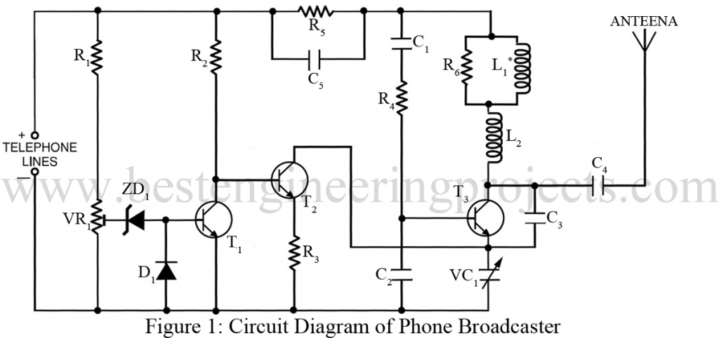
An interesting circuit design that is also used as a wireless telephone amplifier, is demonstrated below which has been proven very useful in prying on a telephone conversation and therefore is termed a phone broadcaster circuit.
The more amazing or we can say a comforting fact about the phone broadcaster circuit design is that it draws the power essential to operate the circuit directly from the active telephone lines. Therefore, it avoids additional expenses in external battery and prevents the circuit from the extra bulkiness of other power supplies.
Circuit Description of Phone Broadcaster Circuit
To add more, though the circuit phone broadcaster derives its power from the telephone line, it does not harm the overall performance of the telephone. This tiny circuit can be easily fitted inside a telephone connection box of 3.5 cm x 5 cm, using a single-IC type Veroboard.

Two sections: the automatic switching section and the FM transmitter section form the entire circuit of the telephone broadcaster.
Automatic Switching Section | Phone Broadcaster Circuit
The resistors R1 to R3, transistors T1 and T2, zener D2 and diode D1, and preset VR1 comprise the automatic switching section. As shown in the circuit diagram of the phone broadcaster, resistor R1, along with the preset VR1, works as a voltage divider. If the voltage across the telephone wire is 48V DC, the voltage at the wiper of preset VR1 varies from 0 to 32V which can be adjusted.
The switching voltage of the circuit phone broadcaster depends on the Zener breakdown voltage and the switching voltage of the transistor. In this circuit below, the voltage values are 24V and 0.7V respectively. So that the transistor T1 may conduct, the preset voltage of VR1 must be adjusted above 24.7 volts and Zener breakdown occurs, resulting in conduction.
Consequently, the transistor T1 cuts off T2, as its (of T1) collector gets attracted towards the negative supply. At this stage of the circuit, if we pick the handset of the telephone, the transistor T1 also cuts off as the line voltage drops to about 11V. As a result, transistor T2 gets forward biased through resistor R2 and offers transistor T3 with a DC path in the FM transmitter section.
FM Transmitter Section | Phone Broadcaster Circuit
The coil L1, oscillator transistor T1, and a few other components comprise the low-power FM transmitter section. In this circuit, transistor T2 acts as an electronic ‘on’/’off’ switch, and transistor T3 works as a common-emitter RF oscillator. The oscillator frequency is automatically adjusted by the audio signal available across the telephone line via transistor T2 along with its series biasing resistor R3. The RF signal after modulation is fed to the antenna. Finally, the entire phone conversation can be heard on the other side of the FM receiver remotely when the frequency matches the FM transmitter frequency.
Check out other phone/telephone related circuits posted on bestengineeringprojects.com
- Cell Phone Jammer Circuit
- Telephone Amplifier Circuit
- Add on Device For Telephone
- Telephone Converter Circuit
- Telephone Spy
NOTE:
The addition of resistor R5 and capacitor C5 was recommended for error-free service to avoid the engaged tone of telephone service during practical application.
PARTS LIST FOR PHONE BROADCASTER CIRCUIT
| Resistor (all ¼-watt, ± 5% Carbon) |
| R1, R2, R4 = 47 KΩ
R3 = 100Ω R5 = 22 KΩ R6 = 1 MΩ VR1 = 100 KΩ |
| Capacitors |
| C1 = 0.01 µF (Ceramic Disc)
C2 = 330 pF (Ceramic Disc) C3 = 5.6 pF (Ceramic Disc) C4 = 10 pF (Ceramic Disc) C5 = 0.22 µF (Ceramic Disc) VC1 = 50 pF (trimmer) |
| Semiconductors |
| T1 – T3 = BC548 (General Purpose NPN Silicon Transistor)
D1 = 1N4007 (Rectifier Diode) ZD1 = 24V, 400 mA zener diode |
| Miscellaneous |
| L1 = 45 turns, 38 SWG wire over 1MΩ, 1Watt carbon resistor
L2 = Air core, 3 turns, 21 SWG 12mm diameter |
can u please provide some more information about this topic?
i am interested to do this for my project.
Can you please elaborate, what’s type of detail you are searching for?
I think, the detail given here is enough.
i want to know that, y we r using especially that components for broadcasting and how it works during the process?