In the article you will learn about Parity Generator Checker | Error Detector IC SN74180, its key parameter, application and working.
Description of Parity Generator Checker | Error Detector
The parity bit method of error detection depends on a fixed word length in which all of the 1s are added together. For even parity, the sum of these logic 1s must be even; for odd parity, it must be odd. To assure that the sum is respectively odd or even, a separate parity bit is transmitted that is set either to 1 or to 0, whichever is required to make the sum of the 1s even or odd.
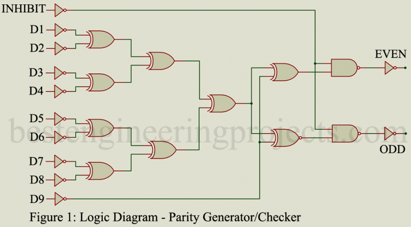
The logic diagram of Figure 1 shows a simple 9-bit parity generator/checker. The nine inputs are added through a tree arrangement of exclusive OR circuits. When the sum of the 1s is even the “even” output will be a logic 1. When the sum is odd, the “odd” output will be a logic 1. The inhibit signal is used to prevent operation of the parity generator/checker, and when its input is 1, both the even and the odd output will be at 0.
When used as a parity generator, the parity bit is supplied along with the data to generate an even or odd parity output. When this IC is used as a parity checker, the received data bits and parity bits are compared for correct parity. The even or odd outputs then indicate an error in the received data. It is possible to cascade a series of these ICs to check parity or generate parity for longer words.
Key parameters of Parity Generator Checker | Error Detector
- Maximum power dissipation: 500 mW is typical for high voltage CMOS devices.
- Quiescent current: The total current drawn by the IC when it is not in operation. 0.04 uA is typical at a 5V power supply for high-voltage CMOS.
- Propagation delay time: The time between data input and data output. A typical value is 350 ns for high voltage CMOS devices at 5V power supply.
- Inhibit-to-output delay time: The time required from the application of the inhibit signal until the output of both even and odd terminals is 0. 150 ns is a typical value for high voltage CMOS.
Applications
This type of IC is used whenever error correction and detection of digital data must be performed. It is frequently used in digital communications systems, at the I/O ports of computer systems, and in specific portions of digital computers themselves.
Representative Part Number: Texas Instruments SN74180
Comments
Although the illustration of Figure 1 shows a 9-bit parity generator/checker, ICs are also available for 8-bit, 12-bit, 16-bit, etc., word length operations.
