The project aims at developing an inventory management system using the C language that enables an organization to maintain its inventory. The project inventory management system demonstrates the creation of a user interface of a system, without the use of C Graphics library. The application uses basic C functions to generate menus, show message boxes and print text on the screen. To display customized text with colors and fonts according to application requirements, functions have been created in the application, which fetch the exact video memory addresses of a target…
Read MoreRecord Entry System Using C
The objective of the record entry system is to develop a login-based record keeping system, which has nested menus and different interface for different sets of users. The application record entry system contains separate interface defined for an administrator and employees. The application provides a basic menu, which has menu options for both types of users. According to the selection made by the user, the user is prompted to enter his login name and password. On successfully validation the user name and password, a menu is displayed to the user…
Read MoreSnake Game Using C
/* forward your comments to bestengineeringprojects.com */ To setup the graphics library: copy graphics.h to include folder and lbgi.a to library folder. Click Here To Download graphic.h and lbgi.a for linker parameters add these in project: -lbgi -lgdi32 -lcomdlg32 -luuid -loleaut32 -lole32 then start coding The Library files used is provided by Computer Science Depart. of Colorado University ( http://www.cs.colorado.edu/~main/bgi/ ) The Code: Now you can simply paste following code in the source file and compile , execute it. ( If you would like to know more about the code…
Read MoreSound Operated On-Off Switch
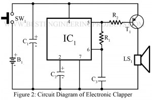
Various remote control-based projects are already posted on bestengineeringprojects.com. Now here is a unique remote control circuit called a sound operated on-off switch and it responds only particular frequency of sound (4.5 kHz) and can control the device from a distance of up to 4.6 meters (15 feet). Most sound-operated switches use clap sound or voice to activate the remote control. Tone frequency generated by clapping or a voice control is not constant and designing a receiver circuit for a particular or ordinary clap or voice is very difficult. To…
Read MoreMicrophone Amplifier Using Op-amp 741
Various types of basic electronic projects using operational amplifier-based projects are already posted on bestengineeringprojects.com. Now, here is another basic project using an operational amplifier called a microphone amplifier using 741. The circuit microphone amplifier amplifies weak electric signals converted by the microphone to the necessary level. More other circuits using microphones are posted on bestengineeringprojects.com Dynamic Microphone Preamplifier Circuit Listening Bug Circuit using op-amp LM386 DIY Hearing Aid Circuit using 555 Sound Activated 0-30 Minutes Timer Circuit Arduino-Based Automatic Call Answering Machine Sound detector circuit using op-amp 741 Circuit…
Read MoreThermal Touch Switch using op-amp 741
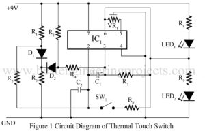
Various types of switch circuits like a light operated switch, sound operated switch, etc is already posted on www.bestengineeringprojects.com. Now here is a thermal touch switch that automatic on and off due to the increase and decrease of pre-defined temperature. This type of circuit is useful to operate fans, cooler, etc. Circuit description of thermal touch switch using operational amplifier 741 The circuit comprises an operational amplifier IC (IC1), silicon diode (D1 and D2), and a few passive components to complete the circuit. Diode D1 is used here as a…
Read MoreVoltage into Frequency Converter Circuit using 741 IC
IC 741 is the most used and popular operational amplifier IC, because of its unique feature and low price. Various op-amp 741-based projects are already posted in the operational amplifier-based projects section. Now, here is a simple project using a couple of op-amps 741 IC called voltage into frequency converter. Description of voltage into frequency converter Circuit using 741 IC The circuit of voltage into frequency converter consists of a couple of op-amp 741, a couple of transistors, and a few passive components (resistors). The voltage of 0.5V to 15V…
Read MoreTelephone Diary using C++
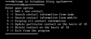
The project telephone diary using C++ stores contact information of person. The program telephone diary has used file system to store contact information in disk. It stores ID, Name, Address, Phone, Mobile and Email of a person. This project allows us to add, update, delete and search particular record of person. We can search contact information from person name and mobile number. Again, we can list out all contact in alphabetical order choosing appropriate option in program. Again, we can update and delete existing contact information on the basis of…
Read MoreEmployee Management System Using C++
Introduction to Employee Management System Using C++ Employ management system using C++ is a menu-driven program that allows us to add, update, delete and search records of an employee working in an organization. The program employee management system stores employee ID, name, post, department, and salary of the employee. Initially, it has no data. Thus, we have to add employee records choosing appropriate options in this program (i.e. selecting option #1). Previously we had posted Employee Management System Using C with the same features. Employee Management system using C++ program…
Read MoreWind Sound Generator Using IC 741
Various sound generator projects is already posted in bestengineeringprojects.com in alarm and sound generator section. Now here is one another sound generator circuit using most popular and versatile operational amplifier IC 741. The circuit posted here is of wind sound generator using IC 741 produces wind sound. Circuit Description of Wind Sound Generator Using IC 741 The circuit of wind sound generator comprise operational amplifier 741, two NPN transistors (BC148) and some passive components (resistors and capacitors). Transistors T1 and T2 generate wind sound. A jumper is connected to emitter…
Read More


