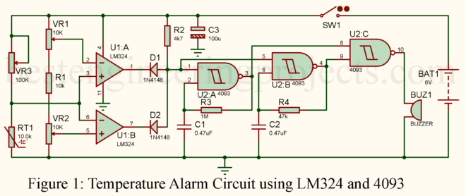
In this project, we are going to do a step-by-step guide to building a temperature alarm circuit whereby when it hits the specified temperature, it would start to trigger a buzzer. The entire circuit will be centered around an LM324 operational amplifier and 4093 NAND gate IC. This digital electronics project teaches you how to create a temperature-based alert system, useful in many applications, such as temperature-sensitive areas where an audible alert can help signal high temperatures. Components Required for Temperature Alarm Circuit To build this digital electronics project, you’ll…
Read MoreHow to Build a Precision Amplifier Circuit Using OP07 and CD4052 Multiplexer
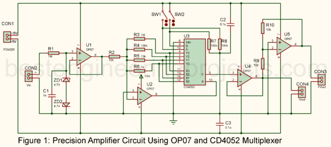
In many electronics projects, you need to amplify weak signals without adding noise. This article will guide you through building a precision amplifier circuit using OP07 operational amplifiers and a CD4052 multiplexer. The great thing about this design is its ability to switch between different input signals, making it versatile for applications like sensor interfacing, data collection, and instrumentation. What is a Precision Amplifier? Simply put, a precision amplifier boosts small signals—like those from sensors—without adding much noise or distortion. These amplifiers are often used when accuracy matters, such as…
Read MoreDIY High-Gain Audio Amplifier: How to Build a Sound Booster for Stealth Recording
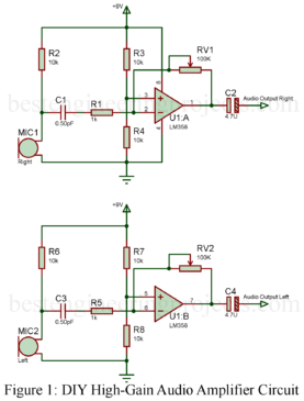
Are you looking to amplify faint sounds or whispers from across the room? Whether you’re into audio surveillance, DIY electronics, or just curious about boosting sound levels for personal projects, this guide will walk you through building a high-gain audio amplifier—the ultimate sound booster for stealth recording. With this tiny gadget, one can turn any modern recording setup into a powerful tool that will be capable of picking up even the faintest sound or conversation present in the room. Be it for surveillance, sound recording, or just playing around with…
Read MoreEnhancement vs. Depletion MOSFETs: Pros, Cons, and Key Differences Explained
MOSFETs, or Metal-Oxide-Semiconductor Field-Effect Transistors, are widely used in many electronic applications because of their practical switching and amplifying functions. Two kinds of MOSFETs are used: the Enhancement MOSFET and the Depletion MOSFET. Each type differs in characteristics, advantages, and disadvantages. Here is a short overview to compare the pros and cons of enhancement and depletion MOSFETs to decide which will suit your application. Enhancement MOSFETs Starting from The enhancement, MOSFETs are the most applied type in today’s electronics. They are “normally off” when V_GS = 0, and thus, no…
Read MoreSolar Powered LED Garden Light Circuit: Easy DIY Project for Beginners
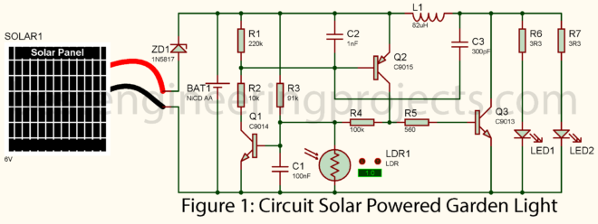
Harnessing the sun’s power to light up your garden is eco-friendly and a fantastic DIY project for beginners. In this tutorial, we’ll walk you through building a solar-powered LED garden light circuit that automatically turns on at dusk and switches off at dawn. With a few electronic components and simple steps, you can create your sustainable lighting system that saves energy and reduces electricity bills. Why Build a Solar-Powered Garden Light? Solar-powered garden lights are an excellent choice for anyone who wants to add aesthetic lighting to their outdoor spaces…
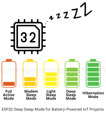
Read MoreHow to Use ESP32 Deep Sleep Mode for Battery-Powered IoT Projects
The ESP32 is one of the best choices for IoT projects because of its built-in Wi-Fi, Bluetooth, and energy-saving features. In battery-powered applications, deep sleep mode is especially useful for reducing power consumption while the device waits for a trigger to wake up. The following tutorial covers how to implement deep sleep mode, discuss differences from other low-power modes like light sleep and hibernation, configure wake-up sources, and manage data across sleep cycles to help IoT devices with long runtime on a single charge. Why Use Low Power Modes? Low-power…
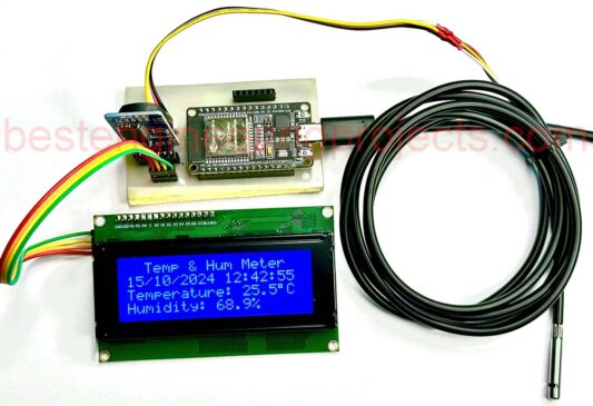
Read MoreESP32 Temperature and Humidity Meter with Real-Time Display
Are you looking for an easy project to monitor environmental conditions in real-time? This project will show you how to create an ESP32 Temperature and Humidity Meter whose readings will be received in real-time. This small, inexpensive project requires the ESP32 microcontroller, CHT8305 temperature and humidity sensor, a 20×4 I2C LCD display, and a DS3231 Real-Time Clock (RTC) module. The system toggles: it will present the current temperature, humidity, date, and time for 10 seconds and then show the maximum and minimum values of the temperature and humidity for 5…
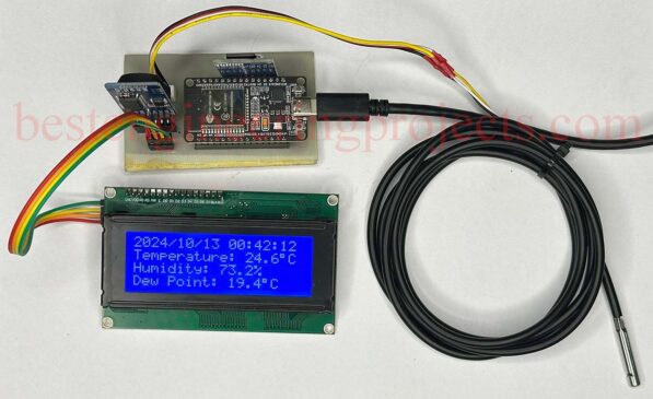
Read MoreBuild a Temperature, Humidity, and Dew Point Data Logger with ESP32
In this project, we will build a temperature, humidity, and dew point data logger with ESP32. This system will show the current time on a 20×4 LCD along with temperature, humidity, and dew point and periodically log the data on an SD card. In the design, an ESP32 microcontroller is used, together with a DS3231 RTC module for correct time representation and a CHT8305 sensor for temperature and humidity readings. The temperature, humidity, and dew point data logger with ESP32 is a versatile project useful in applications such as environmental…
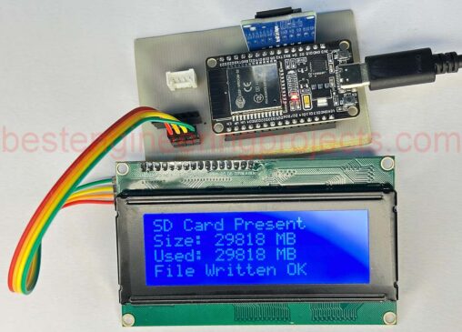
Read MoreSD Card Interfacing with ESP32
In embedded systems, time information is monitored through logging and data storage. Most microcontrollers, including ESP32, can store sensor readings, logs, or configuration files on SD cards. In this tutorial, we will explain how to interface an SD card with the ESP32 microcontroller and display the card’s status along with volume on a 20×4 I2C LCD. We will then create a text file on the SD card and write some data. Figure 1: Components of esp32 and SD card Interfacing Hardware Components Required ESP32 development board SD card module SD…
Read MoreHow to Interface Multiple I2C LCD to Arduino
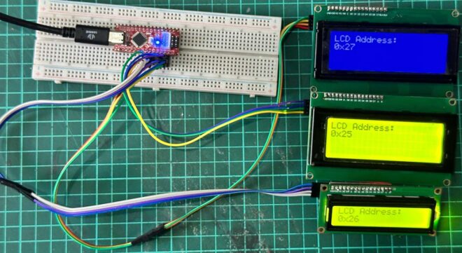
Sometimes, we must connect multiple LCDs to Arduino to display parameter readings or messages. In the tutorial “How to Interface Multiple I2C LCDs to Arduino,” you will learn how to interface multiple 16×2 I2C LCDs to your Arduino. After completing this tutorial, you will able to know: Select a different address for a 16×2 or 20 x 4 I2C LCD. How to interface multiple I2C LCDs with your Arduino? How to select a different address for different 16×2 LCD We have to configure some hardware to select the address of…
Read More