The Marconi antenna is used primarily with frequencies below 2 MHz. The difference between the Marconi antenna and the Hertz antenna is that the Marconi type requires a conducting path to the ground, and the Hertz type does not. The Marconi antenna is usually a quarter-wave grounded antenna or any odd multiple of a quarter wavelength.
Effects of Ground Reflection in Marconi Antenna
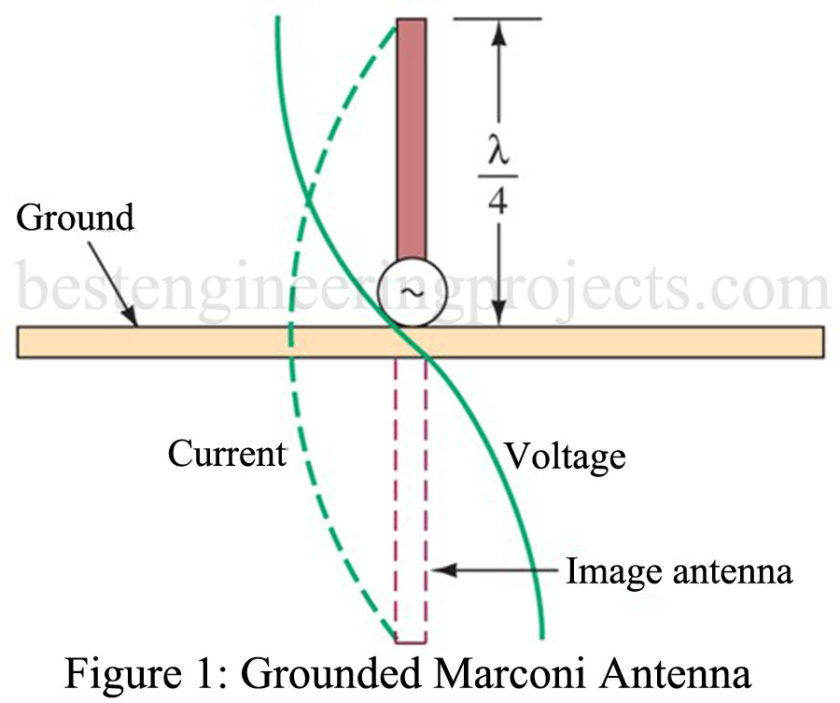
A Marconi antenna used as a transmitting element is shown in Figure 1. The transmitter is connected between the antenna and the ground. The actual length of the antenna is the one-quarter wavelength. However, this type of antenna, by its connection to the ground, uses the ground as the other quarter wavelength, making the antenna electrically a half wavelength. This is so because the earth is considered to be a good conductor. There is a reflection from the earth that is equivalent to the radiation that would be realized if another quarter-wave section were used. The reflection from the ground looks like it is coming from a section beneath the ground. This is known as the image antenna and is shown in Figure 1. By use of the Marconi antenna, which is a quarter-wave in actual physical length, the half-wave operation may be obtained. All of the voltage, current, and impedance relationships characteristic of a half-wave antenna will also exist in this antenna. The only exception is the input impedance, which is approximately
at the base. The effective current in the Marconi grounded antenna is maximum at the base and minimum at the top, while voltage is minimum at the bottom and maximum at the top.
When the conductivity of the soil in which the Marconi antenna is supported is very low, the reflected wave from the ground may be greatly attenuated. A great attenuation of the reflected signal is highly undesirable. To overcome this disadvantage, the site location could be moved to a location where the soil possesses a high conductivity. If it is impractical to move the site, provisions must be made to improve the reflecting characteristics of the ground by installing a buried ground screen.
The Counterpoise
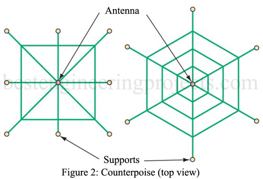
When an actual ground connection cannot be used because of the high resistance of the soil or a large buried ground screen is impractical, a counterpoise may replace the usual direct ground connection. This is required for Marconi antennas mounted at the top of tall buildings. The counterpoise consists of a structure made of wire erected a short distance above the ground and insulated from the ground. The size of the counterpoise should be at least equal to, and preferably larger than, the size of the antenna.
The counterpoise and the surface of the ground form a large capacitor. Due to this capacitance, antenna current is collected in the form of charge and discharge currents. The end of the antenna normally connected to the ground is connected through the large capacitance formed by the counterpoise. If the counterpoise is not well insulated from the ground, the effect is much the same as that of a leaky capacitor, with a resultant loss greater than if no counterpoise were used.
Although the shape and size of the counterpoise are not particularly critical, it should extend for equal distances in all directions. When the antenna is mounted vertically, the counterpoise may have any simple geometric pattern, such as is shown in Figure 2. The counterpoise is constructed so that it is nonresonant at the operating frequency. The operation realized by use of either the well-grounded Marconi antenna or the Marconi antenna using a counterpoise is the same as that of the half-wave antenna of the same polarization.
Radiation Pattern of Marconi Antenna
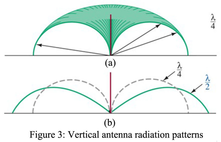
The radiation pattern for a Marconi antenna is shown in Figure 3(a). It is omnidirectional in the ground plane but falls to zero off the antenna’s top. Thus, a large amount of energy is launched as a ground wave, but appreciable sky-wave energy also exists. By increasing the vertical height to , the ground-wave strength is increased, as shown in Figure 3(b). The maximum ground-wave strength is obtained by using a length slightly less than
. Any greater length produces high-angle radiation of increasing strength, and horizontal radiation is reduced. At a height of
there is no ground wave.
Loaded Antennas
In many low-frequency applications, it is not practical to use an antenna that is a full quarter wavelength. This is especially true for mobile transceiver applications. Marconi antennas less than a quarter wavelength have a highly capacitive input impedance, and they become inefficient radiators. The reason for this is that a highly reactive load cannot accept energy from the transmitter. It will be reflected and will set up high-standing waves on the feeder transmission line. An example of this is a Marconi antenna, which exhibits an input impedance of about
at its base.
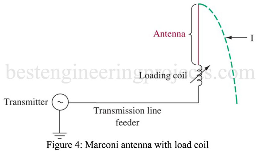
To remedy this situation, the effective height of the antenna should be , and this can be accomplished with several different techniques. Figure 4 shows a series inductance that is termed a loading coil. It is used to tune out the capacitive appearance of the antenna. The coil-antenna combination can thus be made to appear resonant (resistive) so that it can absorb the full transmitter power. The inductor can be variable to allow adjustment for optimum operation over a range of transmitter frequencies. Notice the standing wave of the current shown in Figure 4. It has a maximum amplitude at the loading coil and thus does not add to the radiated power. This results in heavy I2R losses in the coil instead of this energy being radiated. However, the transmission line feeding the loading coil/antenna will be free of standing waves when the loading coil is properly tuned.
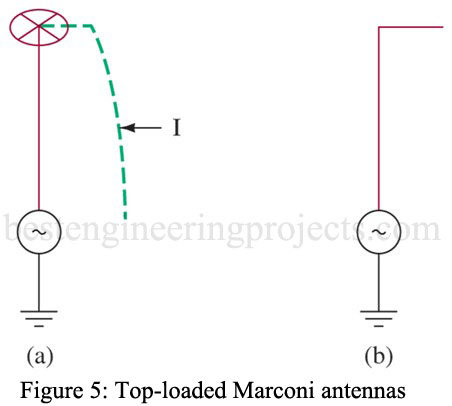
A more efficient solution is the use of top-loading, as shown in Figure 5(a). Notice the high-current standing wave now exists at the base of the antenna so that maximum possible radiation now occurs. The metallic spoked wheel at the top adds shunt capacitance to the ground. This additional capacitance reduces the antenna’s capacitive reactance since C and XC are inversely related. The antenna can, therefore, be made nearly resonant with the proper amount of top-loading. This does not allow for convenient variable frequency operation as with the loading coil, but it is a more efficient radiator. The inverted L antenna in Figure 5(b) accomplishes the same goal as the top-loaded antenna but is usually less convenient to physically construct.
