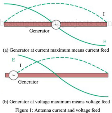
Antenna Feed Lines: If energy is applied at the geometrical center of an antenna, the antenna is said to be center-fed. If energy is applied to the end of an antenna, it is known as an end-fed antenna. Although energy may be fed to an antenna in various ways, most antennas are either voltage fed or current-fed. When energy is applied to the antenna at a point of high circulating current, the antenna is current-fed. When the generator energy is applied to a point of high voltage on the antenna, the antenna is voltage-fed. Both of these types of feed are shown in Figure 1.
It is seldom possible to connect a generator directly to an antenna. It is usually necessary to transfer energy from the generator (transmitter) to the antenna by use of a transmission line (also called an antenna feed line). Such lines may be resonant, nonresonant, or a combination of both types.
Resonant Antenna Feed Lines
The resonant transmission line is not widely used as an antenna feed method because it tends to be inefficient and is very critical concerning its length for a particular operating frequency. However, in certain high-frequency applications, resonant feeders sometimes prove convenient.
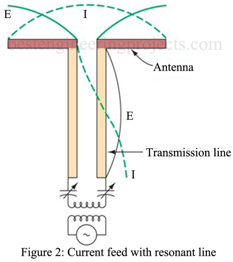
In the current-fed antenna with a resonant line, as shown in Figure 2, the transmission line is connected to the center of the antenna. This antenna has a low impedance at the center and, like the voltage-feeding transmission line, has standing waves on it. Constructing it to be exactly a half wavelength causes the impedance at the sending end below. A series resonant circuit is used to develop the high currents needed to excite the line. Adjusting the capacitors at the input compensates for slight irregularities in line and antenna length.
Although this example of an antenna feed system is a simple one, the principles described apply to antennas and lines of any length provided both are resonant. The line connected to the antenna may be either a two-wire or coaxial line. In high-frequency applications, the coaxial line is preferred due to its lower radiation loss.
One advantage of connecting a resonant transmission line to an antenna is that it makes impedance matching unnecessary. In addition, it makes it possible to compensate for any irregularities in either the line or the antenna by providing the appropriate resonant circuit at the input. Its disadvantages are increased power losses in the line due to high standing waves of current, increased probability of arc-over because of high standing waves of voltage, very critical length, and production of radiation fields by the line due to the standing waves on it.
Nonresonant Antenna Feed Lines
The nonresonant feed line is the more widely used technique. The open-wire line, the shielded pair, the coaxial line, and the twisted pair may be used as nonresonant lines. This type of line has negligible standing waves if it is properly terminated in its characteristic impedance at the antenna end. It has a great advantage over the resonant line in that its operation is practically independent of its length.
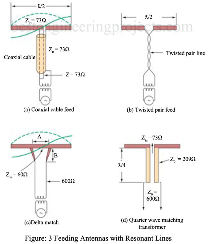
The illustrations in Figure 3 show the excitation of a half-wave antenna by non-resonant lines. If the input to the center of the antenna in Figure 3(a) is and if the coaxial line has a characteristic impedance of 73 Ω, a common method of feeding this antenna is accomplished by connecting directly to the center of the antenna. This method of connection produces no standing waves on the line when the line is matched to a generator. Coupling to a generator is often made through a simple untuned transformer secondary.
Another method of transferring energy to the antenna is through the use of a twisted pair line, as shown in Figure 3(b). It is used as an untuned line for low frequencies. Due to excessive losses occurring in the insulation, the twisted pair is not used at higher frequencies. The characteristic impedance of such lines is about .
Delta Match
When a line does not match the impedance of the antenna, it is necessary to use special impedance matching techniques such as Smith chart applications. An example of an additional type of impedance matching device is the delta match, shown in Figure 3(c). Due to inherent characteristics, the open, two-wire transmission line does not have a characteristic impedance (Zo) sufficiently low to match a center-fed dipole with Zin = . Practical values of Zo for such lines lie in the range
to
. To provide the required impedance match, a delta section (shown in Figure 3(c)] is used. This match is obtained by spreading the transmission line as it approaches the antenna. In the example given the characteristic impedance of the line is
, and the center impedance of the antenna is
. As the end of the transmission line is spread, its characteristic impedance increases. Proceeding from the center of the antenna to either end, a point will be reached where the antenna impedance equals the impedance at the output terminals of the delta section. Recall that the antenna impedance increases as you move from its center to the ends. The delta section is then connected at this distance to either side of the antenna center.
The delta section becomes part of the antenna and, consequently, introduces radiation loss (one of its disadvantages). Another disadvantage is that trial-and-error methods are usually required to determine the dimensions of the A and B sections for optimum performance. Since both the distance between the delta output terminals (its width) and the length of the delta section is variable, adjustment of the delta match is difficult.
Quarter-Wave Matching
Still another impedance matching device is the quarter-wave transformer, or matching transformer, as shown in Figure 3(d). This device is used to match the low impedance of the antenna to the line of higher impedance. The quarter-wave matching section is effective only between a line and purely resistive loads.
To determine the characteristic impedance (Z’0) of the quarter-wave section, the following formula
where = characteristic impedance of the matching line
Zo = impedance of the feed line
RL = resistive impedance of the radiating element
For the example shown. Z’0 has a value slightly over . With this matching device, standing waves will exist on the
section but not on the
line. The use of stub matching techniques as another alternative.
This matching technique is useful for narrowband operation, while the delta section is more broadband in operation


