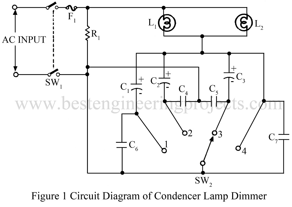
Various type of dimmer circuit is already available online, and the idea of lamp dimmer is not new to electronics hobbyist. This light dimmer circuit is very efficient because no power is dissipated in the resistive elements. In SCR light dimmers the firing angle is controlled as a result of which the waveform is distorted. But it is not so with this circuit.
The load in this case always works with sine wave irrespective of power delivered to the load or the type of load. The brightness of the lamp can be controlled in many steps. Two lamps, each of 25W, can be operated together. If the wattage of the load is more, the capacitors need slight adjustments. Using the suitable value of capacitors any type of load can be controlled. Further, the load is protected from the transient.
Check out other dimmer circuits posted in bestengineeringprojects.com
Description of Lamp Dimmer Circuit
C1, C2, and C3 are so chosen, so as to given ¼, ½ and 3/2 of the total power to the load. The capacitors C4 – C7 absorb transient voltage and protect the lamp.
Unlike SCR lamp dimmer, this circuit does-not need any triggering circuit. If needed, the fuse of a suitable rating can be included in the circuit.

PARTS LIST OF LIGHT DIMMER CIRCUIT
|
Resistor |
|
R1 = 200KΩ/2W |
|
Capacitors |
|
C1 = 2 µF, 400V, AC C2 = 3.3 µF, 400V, AC C3 = 4.7 µF, 400V, AC C4 – C7 = 0.1 µF, 400V, AC |
|
Miscellaneous |
|
SW1 = DPDT Switch On-Off SW2 = 1-Pole 4-Wat Switch |