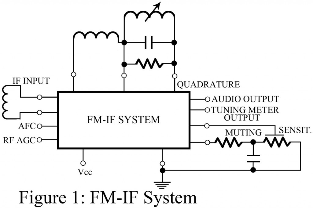
This IC includes a 3-stage FM-IF amplifier/limiter arrangement with level detectors for each stage and a balanced quadrature FM detector. As illustrated in Figure 1, the quadrature-tuned circuit requires two external coils, a capacitor and resistor and a single adjustment. Most ICs of this type also include an audio amplifier as well as a driving circuit for the tuning meter output, automatic frequency control (AFC) for the FM tuner, and AGC for the RF amplifier stage.
The muting sensitivity control is optional and provides automatic muting (squelching), if desired. An internal power-supply regulator makes it possible to use any supply voltage between 8 and 18 V. The amount of distortion obtained with this IC depends mostly on the phase linearity of the quadrature-detector coil.
Key Parameters of FM – IF System
- Input limiting voltage: – The voltage at the input that will cause limiting of the FM-IF signal. 10 µF is a typical value.
- AM rejection: – The rejection of amplitude modulation with an input voltage of 100 mV, with 30% AM modulation at 400 Hz. 55 dB is typical.
- Recovered audio voltage: – The amplitude of the audio output signal when the input signal reaches the limiting level with 400 Hz audio, FM modulated at 25 kHz. Typical values range between 300 and 500 mV
- Total harmonic distortion: – Audio distortion at all frequencies with the same input conditions described for. A typical value is 0.5% with a single-tuned input circuit or 0.1% with a double-tuned input circuit.
- Signal-to-noise ratio: – Measured with a deviation of ±75 kHz. 65 dB is typical.
Applications of FM – IF System
This IC is used in all types of FM receivers and intended for 10.7 MHz IF frequencies.
Comments on FM – IF System
To provide sufficient FM-IF selectivity, most manufacturers of FM receivers use a narrowband filter before the IF input stage. Because of the very high gain of this IC, the layout on the PC board and the location of bypass and decoupling capacitors and grounds can become critical.
