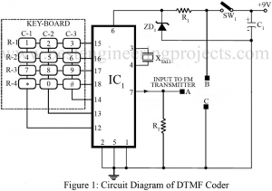
Different gadgets have been introduced to meet our requirements ranging from basic needs to classy needs of humans. With this development in recent years, day by day people has grown more sophisticated. Putting human comfort as a main concern, hereby we have presented a circuit to remotely control several electrical or electronic gadgets connected to it. The unique feature of the circuit DTMF-based remote control system in comparison to other remote control systems like IR remote control is that this circuit employs FM transmission and reception, for this reason, it…
Read MoreCategory: Electronics Projects
Pest Repeller Circuit
No matter how far we try to escape from pest’s trap or we attempt to clean the surrounding around us, we get eventually bothered being followed everywhere from kitchen to every corners of our house. Different pest repeller circuits have been developed claiming to escort people through this problem. However, pest repeller circuits thus built are found to have low power output resulting poor effectiveness. And, this error gives no solution to our trouble. With this point as our main concern, we have presented a powerful pest repeller circuit that…
Read MoreProximity Detector Circuit Using 555 timer IC
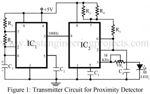
Entire project of proximity detector circuit is built with infrared transmitter, infrared receiver and 555 timer IC (such as using Seimens SFH50638 in TV sets). Proximity detector circuit, anyone can guess the operation performed by this circuit just with the name it is provided with. Infrared diode is the main soul of proximity detector circuit which is used in different equipment’s like burglar alarms, touch-free proximity switches for turning a light on, and solenoid controlled valves for operating a water tap. Description of Proximity Detector Circuit Using 555 timer IC Transmitter…
Read MoreRF Probe Circuit
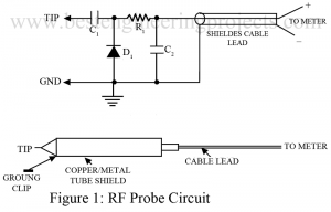
In order to measure the RMS voltage between two specific points, employing heavy and bulky electronic devices sounds unusual. And, therefore a small handy instrument can be used to avoid such situations where the voltage (i.e. RMS) between two points at any distance; large or small can be determined. For this reason, the instrument RF probe circuit has been proven of great help for home users as well as for communication equipment service/design labs. Description and Working of RF Probe Circuit RF probe circuit is just an instrument to measure, in…
Read MoreSimple Drummer Project Using Timer 555
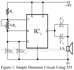
Timer IC 555 is a low-cost high performance and very popular IC and is used in most circuits. On this website, we have posted various electronic projects using ic 555. Now here, is a simple project called Simple Drummer Project Using Timer 555 which gives an hour of entertainment. Circuit Description of Simple Drummer Project Using Timer 555 The circuit of a simple drummer project is built around NE555 followed by a few passive components. The circuit posted here is simply a triggering circuit whose time is adjusted by variable resistor…
Read MoreSimple Siren Circuit using CD7400
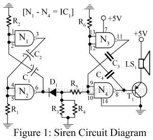
Various types of siren circuit like electronic siren, toy siren, warning siren etc. are already posted in bestengineeringrpojects.com . Now here in one another simple siren circuit using popular and low-cost NAND gate IC (CD4700), which gives hour of entertainment and also can be used in toy. Description of Simple Siren Circuit using CD7400 Siren circuit is build around NAND gate IC (CD7400), a PNP transistor (SK100B) and few passive components. In this circuit we use only half part of IC1. NAND gates N1 and N2 are wired as low…
Read MoreDigital Voltmeter (DVM) Circuit Using ICL-7107
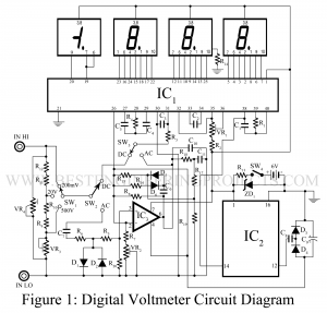
A digital voltmeter (DVM) Circuit displays measurements of AC or DC voltage as discrete numerals instead of a pointer deflection on a continuous scale as in analog instruments. Digital Voltmeter Circuit is a versatile and accurate instrument that is employed in many laboratory measurement applications. Because of the development and perfection of the IC modules, the size, power requirement, and cost of the digital voltmeter as been drastically reduced, and therefore, digital voltmeter circuits can actively compete with the conventional analog instruments in price, portability, and accuracy. Here, in this…
Read MoreAudio Mixer Circuit
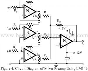
An audio mixer circuit is used to combine output from several microphones/channels into one or more common outputs, usually for public address purposes or while recording. The function of the audio mixture circuit, as the name suggests is to ‘mix’ the different audio signals which are fed to the input for the mixer. In this article, we include various types of audio mixer circuits from the simplest possible transistor audio mixer circuit to the high-end audio mixer preamplifier using an operational amplifier. Description and Working of Audio Mixture Circuit The…
Read MoreAudio Filter Circuit
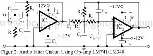
An audio filter circuit is a broadband filter and is also called a wide bandpass filter because its bandwidth is restricted to the audio frequency. Audio filter circuit can be formed by simple cascading high pass filter circuit and low pass filter circuit and is generally the choice for simplicity of design and performance through such a circuit can be realized by a number of the possible circuits. The butter-worth filter is generally used in audio systems which are characterized by a maximally flat-flat filter. Circuit Description of Audio Filter…
Read MorePower Protection Circuit
Being active users of electrical appliances, we can’t deny the fact that they have almost become our right hand to perform our day-to-day activities. Some of these appliances cost us a heavy amount and when these devices fail to operate or get damaged, we suffer heavy economical loss and in addition to that, we lose our helping hand. To avoid this type of issue faced by most people, we have prepared this low-cost circuit “power protection circuit” which saves our dear electrically operated appliances from situations like sudden tripping and…
Read More