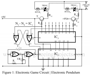
Every person gets a pleasant feeling staring at pendulum when it is oscillating. This pendulum trick can be used in different ways to create a shimmering atmosphere. Electronic technologies guide us through people’s soul and thus help us to win their heart eventually. Here we have presented similar type of game circuit which is used to produce attention-grabbing phenomenon like “dashing light” and pendulum. It sounds quite interesting, don’t you feel so? As everyone knows pendulum oscillates in to and fro motion about a vertical mean position. This process can…
Read MoreCategory: Electronics Projects
Transistor, TRIAC and SCR Tester Circuit
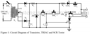
In different types of electronic circuits, you might have seen multiple elements in common. Some of these commonly used semiconductor devices, without which electric circuits are almost incomplete are SCRs, transistors, and TRIACs. In broad electronics circuits when small elements fail to function, its consequence affects the performance of the whole circuit. So, before building the overall circuit, one must be wise enough to check the functioning of circuit elements to avoid future complications. The Transistor, TRIAC, and SCR Tester Circuit presented below assists us in a similar way to…
Read MoreDoor Bell Circuit
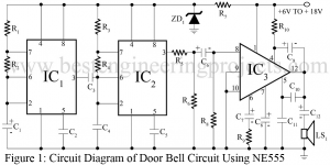
This project describes the constructional and working details of a door bell circuit. The door bell circuit presented here is of 2-notes (modulated sound) type and delivers about 4-watt Musial power at 12 volt. While using it as a door bell circuit, 6V DC supply is enough, which can be derived either from dry battery cells or a battery eliminator. The door bell circuit is flexible enough to work off right from 6V to 18V supply, without change of any component in the circuitry. However, it is important to use…
Read MoreTemperature Deviation Indicator Using OP-AMP 741
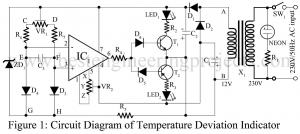
For laboratory work, an accurate temperature deviation indicator is more effective than a sophisticated thermometer. The electronic device temperature deviation indicator using 741 can register a difference of 0.20C between the thermal sources and display it with the appropriate direction of variation. It can be used as a heater coil controller to maintain the equilibrium level. Circuit Description of Temperature Deviation Indicator using op-amp 741 The circuit of temperature deviation indicator using op-amp 741 is simple and self-explanatory. Two silicon diodes (D3 and D4) complete a bridge network and act…
Read MoreLow Pass Filter Circuit | Low Pass Filter Design
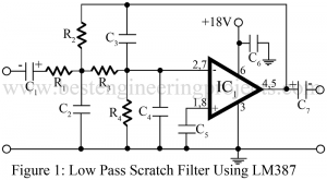
An electric filter or simply a filter is an electric network that passes or allows without loss, the transmission of electric signal within a certain frequency range but stops or disallows transmission of electric signal outside this frequency range. The low-pass filter circuit is also known as a scratch filter and is used to roll off excessive high-frequency noise from worn-out records and tapes. Or we can also define low pass filter as, it passes all frequencies up to a specified frequency, called the cutoff frequencies fc, and reject all…
Read MoreHigh Pass Filter Circuit | Rumble Filter
An electric filter or simply a filter is an electric network that passes or allows without loss, the transmission of electric signal within a certain frequency range but stops or disallows transmission of electric signal outside this frequency range. The three most-popular filters found in audio equipment are the High Pass Filter (rumble filter), Low pass filter (scratch filter), and speech filters. The rumble filter is a high-pass filter, used to suppress the low-frequency rumbling sound associated with old and worn-out turntable and tape deck mechanisms. Here we explain to…
Read MoreBass Treble Circuit
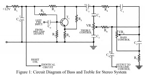
Among different types of amplifiers available in today’s technical world, sometimes we get stuck with the audio frequency amplifiers which provide flat frequency low-frequency notes should be amplified more than the high-frequency note stable). The provision of bass treble is accordingly made to gratify the users and to compensate for the effect of noise that comes along with the signal. The bass treble combination is given a single name; tone control. Circuit Description of Bass Treble Circuit Talking about the bass treble circuit, it is comparatively much simpler and gainful.…
Read MoreWater Level Indicator Circuit using 7-Segment
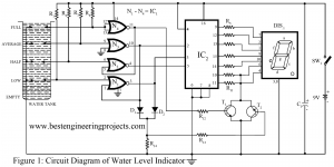
Normally we have seen on different websites, the overall circuit of the water level indicator uses a bar graph or a seven-segment display to indicate the water level. This type of representation using LEDs or digits for water level makes the observer which includes a large number of normal people, difficult to understand. A consequence of using those methods makes the whole effort inadequate. The circuit presented below surmounts this flaw and displays the water level using a seven-segment display, but there is a difference. The water level indicator circuit…
Read MoreElectronic Code Lock Circuit
Using codes for security has been a popular trend recently. A similar type of electronic project is presented right below called the electronic code lock circuit which ensures the use of four digits in the code locking process and these codes are keyed in remotely. The code can be unlocked easily by pressing the right keys and if someone presses the wrong keys, it resets the lock automatically. The complete phenomenon of the electronic code lock systems has been described briefly in the further paragraph. Description and Working of Electronic…
Read MoreAdd on Device For Telephone
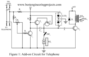
This electronic project, Add on Device For Telephone has multiple applications when used with the telephone lines. Since it is added parallel on the telephone system, it is called add-on device. The circuit add on device for telephone supports three modes of operation: on-hook, off hook, and ringing modes. It also provides the audio-visual indication of these operations. Using the relay, add on device circuit can connect the telephone to a CID (caller identification device). It can also be used to indicate tapping or misuse of telephone lines with the…
Read More