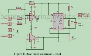
A single beam CRO can be used for simultaneous display of two signals using this simple circuit “Dual Trace Generator Circuit”. The circuit uses one NE555 and two LM741 ICs, besides some passive components. The diode (1N4148) is used to get a 50 percent duty cycle. Circuit Description of Dual Trace Generator Circuit IC 555 is connected in astable mode and acts as a self-switching analog switch between the two signals to be displayed on the CRO. The output of IC 555 is given to the CRO. In order to…
Read MoreCategory: Electronics Projects
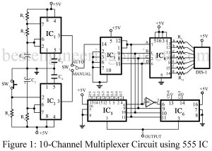
10-Channel Multiplexer Circuit using 555 IC
This project is a low-cost multiplexing system for ten channels. The project 10-channel multiplexer circuit using 555 IC can be used as an add-on device for a single point indicating system. Both auto and manual selection are incorporated with the visual indication of channel number. It is suitable for signals concerning a common line. However, for double-ended signals, the input LOW lines can be made common and the input High lines can be multiplexed. This can be used for thermocouple signals, strain gauges, and any other AC/DC signal in the…
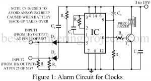
Read MoreAlarm Circuit for Clocks
Here is an alarm circuits for clocks using IC 5387, 5316, LM8361 etc. (any IC giving an alarm and a 1Hz outputs). This circuit has the following advantages over most of other alarm circuits (especially alarm circuits based on IC 555): Working Principle of Alarm Circuit for Clocks The quiescent current is only 0.1 mA which is much less than the 10-15 mA consumed by 555 circuits. Hence the life of 9V battery is increased by above three times. The operation current is also very small. IC 555 based circuitry consumes…
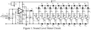
Read MoreSound Level Meter Circuit
The project sound level meter circuit shown here comprises a display circuit for 10-segment resolution i.e. used to indicate sound level up to 10 levels. Recording of sound in the studio involves critical adjustment of recording levels and level of bias current. If the level of sound is very much it may cause some distortion while a low level of sound reduces the SNR (Signal to Noise Ratio) as a result the sound may be too noisy. Care should be taken while recording sound to regulate the signal so that…
Read MoreWireless Mobile Charger Circuit Diagram
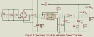
Wireless Mobile Charging is one of the trending topics in the field of electronics thus we also decided to build a Wireless Mobile Charger Circuit Diagram using various commonly available components. The project Wireless Mobile Charger Circuit Diagram posted here can deliver 271mA at 5.2V so you charge mobile phones and also can be used to drive low power loads such as LED1 and LED2 as shown in figure 2. Working Principle of Wireless Mobile Charger Circuit Diagram Wireless Mobile Charger uses the inductive coupling principle. In this principle, two…
Read MoreIR Remote Controller Fan Regulator using AT89C2051
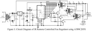
IR Remote Controller Fan Regulator using AT89C2051 is a simple circuit that can control the speed of the fan (you can also use this circuit to control the intensity of light; light dimmer). Previously we have posted a very interesting project on a fan regulator called Light Controlled Digital Fan Regulator that uses torchlight to control the speed of the fan. Now, here we have come with a new idea i.e. control speed fan using the normal IR remote. The project IR Remote Controller Fan Regulator using AT89C2051 uses IR…
Read MoreSpeaker Polarity Test Circuit
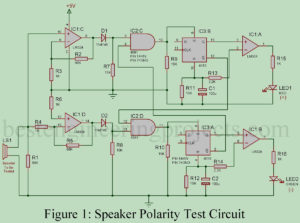
These days, most BEP readers interested in Audio Engineering asked for a circuit that can recognize the polarity (positive and negative terminals) of the speaker. I had also experienced the problem of the polarity of speakers about a few years ago while testing one of my projects. At that time, I had used a multi-meter to test the polarity of the speaker. While testing a multi-meter you have to concentrate on the movement of the speaker cone which is a difficult job especially for a small speaker. For the large…
Read MorePower Saver Circuit Diagram using PIR
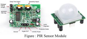
People are always in rush these days and they forget important things like turning the lights off in addition to a few other electrical devices. This results in either an electrical explosion or wastage of power. And, so to eradicate such issues, we have developed a Power Saver Circuit Diagram based on a Passive infrared sensor that employs a PIR motion sensor to detect the presence of human beings and as they leave the room, turn any electrical appliances connected to the circuit after a certain defined time interval. The…
Read MoreMini Projects using IC 741
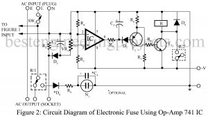
Here in this post, we have compiled some of the verified mini projects using IC 741. The mini-projects using IC 741 listed here can be used as diploma-level as well as high school-level projects. List of Mini Projects using IC 741 1. Electronics Thermometer Using Op-amp 741 IC Here is the circuit diagram of an electronics thermometer using an operational amplifier and silicon diode having a range of -20oC to 125oC.2. Electronic Fuse Using Op-amp 741 Here is an electronic fuse using op-amp 741 which features slow-blow properties, a…
Read MoreAudio Amplifier Circuit Using 555 IC
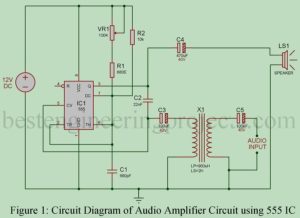
As being electronics hobbyists we all know about timer IC 555. Timer IC 555 is one of the most popular IC of all time because of its application. This IC has various applications like clock pulse generator, time delay circuit, etc. Here, is another application of 555 timer IC i.e. Audio Amplifier using 555. We are going to use a 555 timer IC rather than a conventional amplifier IC because it has unique features like low audio distortion and high efficiency with a high base. PWM is the method by…
Read More