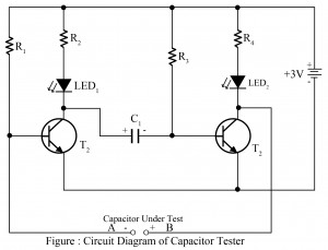
Capacitors are one of the basic components of any electronic project. Now, here we taught you, how to test capacitor whether is short, open or working. The simple circuit of the capacitor tester is built around two general-purpose NPN transistors. This circuit posted here is used to test capacitors up to 1000 µF. The capacitor to be tested is connected at points A and B as shown in the circuit diagram (positive terminal at point B where negative terminal at point A). Working of the circuit Capacitor Tester cum Flasher When…
Read MoreCategory: Easy Electronics Projects
Infrared Remote Controller Using Arduino
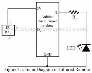
Here is projects called “Infrared Remote Controller Using Arduino” which allow you to control any type of electrical gadget using any infrared remote control. The project posted here records an infrared message from an existing remote control and give output as required. Here, we use EEPROM memory to store the infrared signal code so that we can use this remote even arduino board is disconnected. Circuit Description of Infrared Remote Controller Using Aruino:- The circuit of infrared remote controller is designed using an arduino board and a IR receiver module.…
Read MoreLED Running Light Circuit
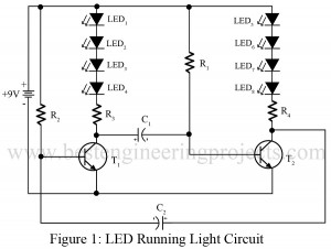
Various types of running or disco lights are already available on bestengineeringprojects.com. Now here very simple LED Running light circuit using two transistors. Circuit Description of LED Running Light Circuit: The entire circuit of LED running light is designed using two general purpose NPN transistors. The design and working of this circuit are very simple and straightforward. Both of these transistors are configured in astable multivibrator mode. Initially when no power supply is connected, both the transistor drives to cut off region and none of this LED glow. But when…
Read MoreNi-Cd Battery Charger
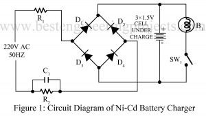
These days many of electrical appliances (watch, RC car, radio etc) use Ni-Cd battery. Here is a simple circuit of Ni-Cd battery charger in the series of easy electronics projects. Circuit Description and working principle of Ni-Cd Battery Charger Basically Circuit of Ni-Cd battery charger is rectifier. The input from AC mains is directly given to the circuit through resistors R1 and R2, where resistor R1 is used to limit the surge current and resistor R2 with capacitor C1 is used to limit the leakage charge current. The output from…
Read MoreMosquito Repeller Circuit
Here is a simple circuit called mosquito repeller in the series of easy electronic project. The circuit of mosquito repeller uses few passive components. Circuit Description and Working Principle of Mosquito Repeller Circuit: The circuit of mosquito repeller is so simple that any-one can understand. The input of 220 volt AC from mains is directly given to the circuit; two resistors are connected in parallel as current divider circuit. Neon lamp is used as indicator to check whether the circuit works properly or not. An aluminum plate is connected to…
Read More


