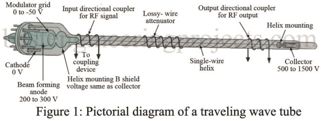
The traveling wave tube (TWT) is a high-gain, low-noise, wide-bandwidth microwave amplifier. Traveling Wave Tube are capable of gains of 40 dB or more, with bandwidths of over an octave. (A bandwidth of one octave is one in which the upper frequency is twice the lower frequency.) TWTs have been designed for frequencies as low as 300 MHz and as high as 150 GHz and continuous outputs to 5 kW. Their wide-bandwidth and low-noise characteristics make them ideal for use as RF and medium-power amplifiers in microwave and electronic countermeasure…
Read MoreCategory: Microwaves
Magnetron Operation | Magnetron
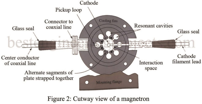
In this article, we will discuss Magnetron and basic Magnetron Operations. The magnetron is an oscillator unlike any other that. A magnetron is a self-contained unit. That is, it produces a microwave frequency output within its enclosure without the use of external components such as crystals, inductors, capacitors, etc. Check out the article on the Application of Microwave. Basically, the magnetron is a diode and has no grid. A magnetic field in the space between the plate (anode) and the cathode serves as a grid. The plate of a magnetron…
Read MoreTroubleshoot Waveguide System
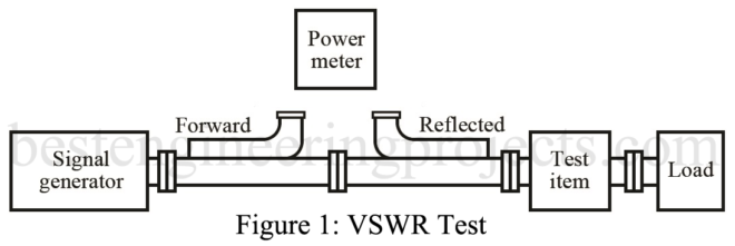
After completing this section, you should be able to troubleshoot the waveguide system. Waveguide problems are very similar to ordinary transmission line problems. The test equipment may look different, but it is doing the same things. A word of caution: Waveguide is commonly used to carry large amounts of microwave power. Microwaves are capable of burning skin and damaging eyesight. Never work on waveguide runs or antennas connected to a transmitter or radar until you are sure the system is off and cannot be turned on by another person. After…
Read MoreMicrowave Integrated Circuits
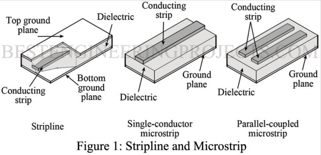
The field of communications now makes heavy use of the frequencies from 1 up to 300 GHz-we shall loosely refer to these as microwave frequencies. At microwave frequencies, even the shortest circuit connections must be carefully considered due to the extremely small wavelengths involved. The thin-film hybrid and monolithic integrated circuits used at microwave frequencies are called MICs (microwave integrated circuits). Check out the article on Applications of Microwaves Microwave Integrated Circuit Overview Obviously, the use of short chunks of coaxial transmission lines or waveguides is not practical for the…
Read MoreRadar Waveform and Range Determination
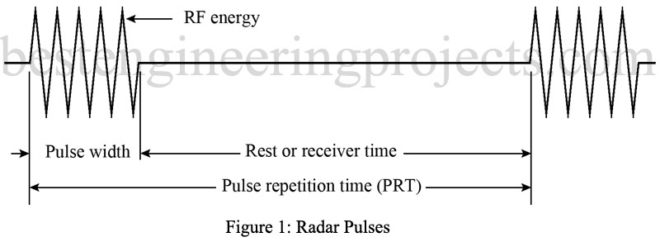
Radar Waveform and Range Determination: A representative radar pulse (waveform) is shown in Fig. 1. The number of these pulses transmitted per second is called the pulse repetition frequency (PRF) or pulse repetition rate (PRR). The time from the beginning of one pulse to the beginning of the next pulse is called the pulse repetition time (PRT). The PRT is the reciprocal of the PRF (PRT = 1/PRF). The duration of the pulse (the time the transmitter is radiating energy) is called the pulse width (PW). The time between pulses…
Read MoreRadar System Parameters
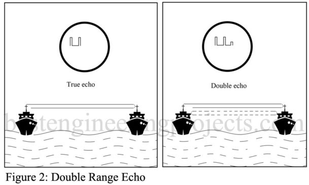
Radar System Parameters: Once the pulse of electromagnetic energy is emitted by the radar, a sufficient length of time must elapse to allow any echo signals to return and be detected before the next pulse is transmitted. Therefore, the PRT of the radar is determined by the longest range at which targets are expected. If the PRT were too short (PRF too high), signals from some targets might arrive after the transmission of the next pulse. This could result in ambiguities in measuring range. Echoes that arrive after the transmission…
Read MoreBasic Radar Block Diagram
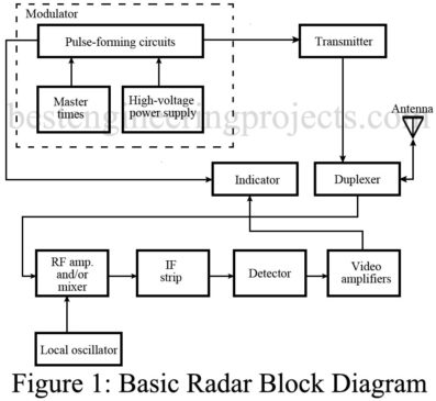
In this article we will discuss about basic radar, and basic radar block diagram. Lets start with basic description of RADAR. What is RADAR? The first practical use of waveguides occurred with the development of radar during World War II. The high powers and high frequencies involved in these systems are much more efficiently carried by waveguides than by transmission lines. The word radar is an acronym formed from the words radio detection and ranging. Radar is a means of employing radio waves to detect and locate objects such as…
Read MoreApplications of Ferrites
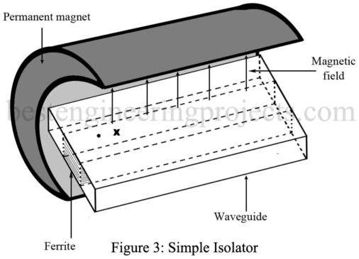
In this article we will discuss about different applications of Ferrites. Applications of Ferrites ATTENUATOR: One application of ferrites is as an attenuator. Figure 1 shows a piece of ferrite placed in the center of a waveguide; a steady magnetic field is applied as shown. This arrangement will attenuate frequencies at the resonant frequency of the electrons in the ferrite, whereas other frequencies will be attenuated very slightly. Changing the strength of the dc field produces a change in the frequency that will be attenuated, although this occurs over a…
Read MoreFerrites | Fundamental Theory of Ferrites
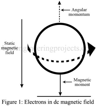
In this article we will discuss about Ferrites, Fundamental Theory of Ferrites and Gyroscopic Action. Introduction of Ferrites Ferrites are compounds of iron, zinc, manganese, magnesium, cobalt, aluminum, and nickel oxides. They are manufactured by pressing into shape the required mixture of the finely divided metallic oxide powders and then firing the shaped mixture at about 2000°F. The product is a ceramic with high electrical resistance. Ferrites behave as iron alloys at low frequencies, but at high frequencies their high electrical resistance prevents eddy currents, and resonance takes place within…
Read MoreIMPATT Diode | Microwave Properties
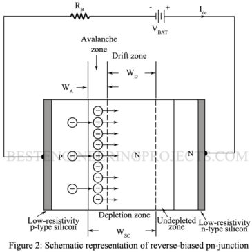
IMPATT Diode: IMPATT is an acronym for impact ionization avalanche transit time. The theory of this device was presented in 1958, and the first experiment diode was described in 1965. The basic structure of a silicon pn-junction IMPATT diode, from the semiconductor point of view, is identical to that of varactor diodes. The important difference between IMPATT and varactor diodes are in their modes of operation and in thermal design. Figure 1 shows a typical dc current versus voltage (I-V) characteristic for a pn-junction diode. In the forward-bias direction, the current increases rapidly…
Read More