Electrical noise measurement has become a very sophisticated process. Specialty electrical/electronics noise measuring instruments that offer many computer-controlled functions are available for thousands of dollars. If you become involved with a large number of measurements, you will become familiar with some of these instruments. In this section, we look at some general methods of noise measurement that can be accomplished with relatively standard laboratory instrumentation. A simple and reliable method of noise measurement is the case where the signal is equal to the noise. At some convenient point in the system, a power meter is connected and a reading is taken of the noise with no signal input. Then an input signal is raised in power level until the monitored power rises by 3 dB (i.e., doubled). At this point, the power level of the signal source is noted. This is equal to the effective input noise level of the system.
Noise Diode Generator
Another electrical noise measurement technique involves using a diode to generate a known amount of noise as predicted by equation . You will recall that this is the equation for shot noise. In this technique, the output impedance of the diode noise generator circuit is matched into the amplifier under test. In these types of measurements, the amplifier is commonly called the device under test or simply DUT. The procedure is first to measure the noise power output of the DUT when the dc current to the noise diode is zero. The dc current is then increased until the DUT noise power output is exactly doubled from the original value. The diode dc current is then used in the following equation to determine the noise ratio of the DUT:
….(Eq. 1)
where R is the input impedance of the DUT and the temperature is 290 K (approximately room temperature).
Exercise 1: An amplifier has an impedance of 50-ohm. Using a matched-impedance diode noise generator, it is found that the DUT has doubled noise output power when the diode has a dc current of 14 mA. Determine the NR and NF for the DUT.
Solution:
Notice that in Ex. 1, the NR is numerically equal to the diode’s current in mA. This occurs when the DUT has an impedance of 50-ohm—a most convenient situation since many RF amplifier systems are designed with a 50-ohm impedance. Keep in mind that NR is a dimensionless ratio, however, and not measured in mA.
Tangential Electrical Noise Measurement Technique
Meters capable of accurately measuring the very low levels involved with noise measurements tend to be expensive and of limited use with regard to other applications. A dual-trace oscilloscope with high sensitivity is an exception to this limitation. Unfortunately, a direct noise reading from the scope results in errors for two reasons:
- Noise is of a highly random nature and is not sinusoidal. Since RMS values are required for noise calculations, the conversion from scope peak-to-peak values by dividing by
is not accurate.
- Since the noise peaks are random, their visibility on the scope is influenced by such things as the scope’s intensity setting, the persistence of the CRT’s phosphor, and the length of the observation.
Figure 1: Scope Display of the same noise signal at two different intensity
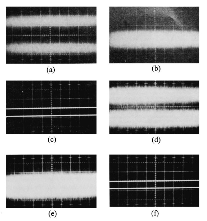
The two displays shown in Fig. 1 show exactly the same noise signal at two different intensity settings. The measurement can be erroneous by as much as 6 dB. A specially developed technique, known as the tangential method, reduces the possible error to less than 1 dB. The noise signal is connected to both channels of a dual-trace scope with alternate sweep capability. As shown in Fig. 2(a), the two displayed signals are set up with both channels identically calibrated. Then their vertical position is adjusted until the dark band between them just disappears [Fig. 1(b)]. Now the noise signal input to both channels is removed, and the resulting separation represents twice the RMS noise. In this case (with a vertical sensitivity of 20 mV/cm), the RMS noise is 0.8 cm x 20 mV/cm / 2, or 8mV RMS. Repeating this process with a different scope intensity setting.
Figure 2: With the tangential method the noise signal is connected to both channels of a dual-channel scope used in the alternate-sweep mode.
(a) The offset voltage is adjusted until the traces just merge.
(b) The noise signal is then removed. The difference in the noise-free traces is twice the RMS noise voltage.
(c) This is repeated at a different intensity to show that the method is independent of intensity.
(d, e, f) Scope settings are: horizontal = 500 ms/cm, vertical = 20 mV/cm.

