Introduction to DIY Resetting Protector Circuit for Computer
With the speed of development in technology, it is no wonder that a number of software have been developed to prevent computers from quick execution of rushed commands which are mostly accidental issues. However, even the most advanced computer programs do not offer protection against the accidental operation of the panel-mounted reset switch. This often leads to incomplete installation of software, improperly closed files, and results in useless memory accumulation in the hard disc. Therefore we need a device which can prevent instant (accidental or normal) resetting of the computer and save us from this technological disaster. The project “DIY Resetting Protector Circuit for Computer” is an inexpensive and effective solution to accidental resetting. When the reset key is pressed for the first time (maybe intentionally) the unit sounds an alarm.
The user can stop the alarm by pressing the same switch again. Thereafter, a panel-mounted LED will start glowing to warn the user that the computer will be reset on the next press.
The “DIY Resetting Protector Circuit for Computer” unit is built around just two easily available CMOS ICs and is compatible with IBM-compatible AT/ XT personal computers and a variety of home computers. A compact PCB, which can easily be accommodated in the computer cabinet, has also been included to simplify the construction.
Description of DIY Resetting Protector Circuit for Computer
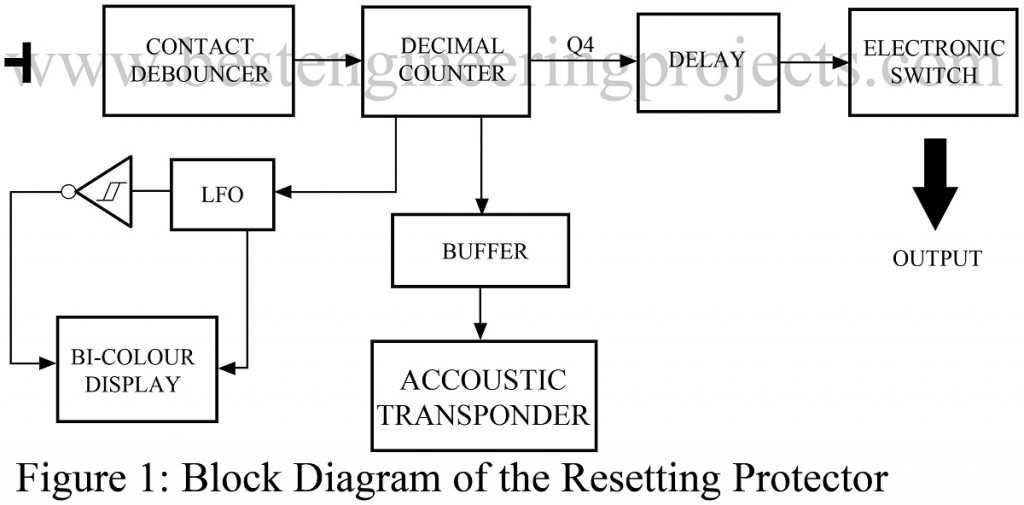
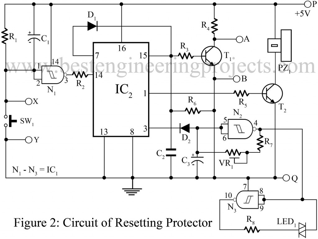
The block diagram of the Resetting protector circuit for the computer is given in Fig. 1 and the complete circuit is given in Fig. 2. The circuit is based on a CD4022 octal decimal counter and a CD4093BE quad 2-input Schmitt NAND gate IC. The circuit is introduced between the reset switch and the PC’s motherboard containing the CPU (refer to Fig. 3). N1 is used as a contact de-bouncer which prevents multiple counting when reset switch S1 is pressed.
When the reset switch is pressed for the first time, the output of N1 goes high momentarily, and the output of IC2 (counter) is incremented by 1. Output pin 1 (Q2) of IC2 goes high and the buzzer is activated through the buffer transistor. When S1 is pressed again, the output Q2 goes low and Q3 (pin 3) goes high, which in turn activates the bi-color LED flasher built around N2 and N3. VR1 is used to adjust the flashing rate. When S1 is pressed again, Q4 (pin 7) of the counter goes high momentarily and applies a high pulse to the reset input of IC2 and resets.
Simultaneously, T1 also starts conducting and the points A and B are shorted momentarily and the computer is reset.
Installation | DIY Resetting Protector Circuit for Computer
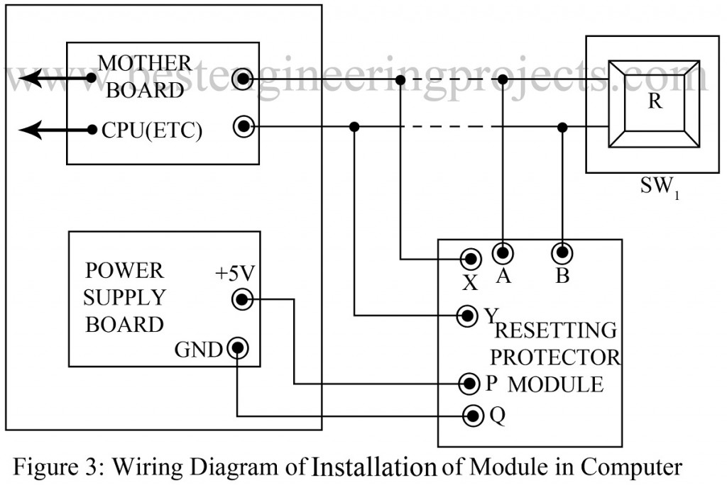
The procedure given here must be followed while installing the circuit to achieve the desired results. Remove the top cover of the computer. The reset switch is mounted on the front panel with one lead connected to the reset circuitry and the other usually to the ground. Cut the wires shown by dotted lines in Fig. 7 and solder them to points X and Y of the module. Solder the wires coming from the reset switch to points A and B. Connect the ground and +5 V terminals of the PSU to points P and Q. Now fix the PCB in a suitable position. In the prototype, it was fixed on the power supply board using a 12 mm spacer. Now replace the cover and switch on the computer. Test the unit by pressing the reset switch.
PARTS LIST
| Resistor (all ¼-watt, ± 5% Carbon) |
| R1, R4, R6, R7 = 100 KΩ
R2 = 10 KΩ R3 = 4.7 KΩ R5 = 1 KΩ R8 = 390 Ω VR1 = 470 KΩ |
| Capacitors |
| C1 = 2.2 µF/12V (Electrolytic Capacitor)
C2 = 0.68 µF (Ceramic Capacitor) C3 = 1 µF/10V (Electrolytic Capacitor) |
| Semiconductors |
| IC1 = CD4093, quad 2-input schmitt NAND gate
IC2 = CD4022, octal decimal counter T1 = BC148B, NPN transistor T2 = BC147B, NPN transistor D1, D2 = 1N4148 (Signal Diode) LED1 = Bi-Color LED |
| Miscellaneous |
| SW1 = PUSH-TO-ON Switch
PZ1 = VK 27 CT Piezo buzzer |


