Imagine being able to control voltage like turning a volume knob, only instead of sound, you’re tuning up or down the power flowing to your electronics. Today, we’re going to create a variable DC power supply with digital controls, using a few nifty components that make this process not just adjustable, but satisfyingly precise.
Building this digitally controlled variable DC power supply might sound complex, but I promise it’s like baking with a recipe—it just takes the right steps. So, let’s dive into it.
Why Go Digital with Voltage Control?
Think of this as the difference between a light switch and a dimmer. With a traditional power supply, you might have to fiddle with knobs to get the exact voltage you want. But with a digital control, you’ve got precise steps. Every click is a calculated step up or down in voltage. Here, we’re aiming for increments from 1.25V all the way to a solid 15.19V. Perfect for those experiments that need a specific voltage without constant adjustments.
What You’ll Need
To build this project, we’ll use a few main players:
- LM317: This adjustable voltage regulator is the muscle of our circuit. It takes in a high voltage and steps it down to whatever output you set.
- 4029 Binary Up-Down Counter: Think of this as the brain. It’s a digital counter that lets us count voltage up or down in a structured way.
- 4093 NAND Gate IC: These gates form the heart of the control signals, like the signals in a traffic light. They tell the counter when to “go up” or “come down.”
- Reed Relays and Resistors: These act as our resistive “ladder.” Each step or combination of steps in the ladder affects the output voltage in small increments.
Each of these components has a role, like different ingredients in a recipe. Alone, they’re just ingredients. Together, they create something new.
Circuit Overview: How It All Works
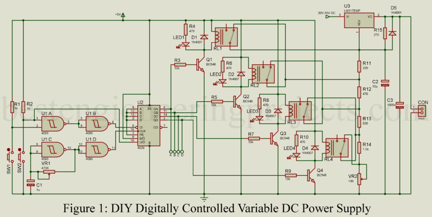
This setup is a combination of parts that all work together. When you press a button, the counter either increases or decreases the voltage. Think of each relay as a step on a ladder; each one activated adds a little more resistance, making the output voltage climb. But when it’s deactivated, we lose that bit of resistance, and the voltage steps down.
Let’s break it down even more.
The LM317 Voltage Regulator
The LM317 is like a gatekeeper. Whatever voltage you put in—anywhere between 20V and 35V—gets processed here. The regulator then outputs a range between 1.25V and 15.19V. This is where the magic formula kicks in:
where is a fixed resistor
while
is made up of a combination of resistors that change depending on which relays are activated.
Digital Counter (4029) with Push-Button Controls
The 4029 counter is like the remote control to our power supply. Want to go up in voltage? Press button S1. Down? Hit S2. Each press sends a pulse that shifts the counter either up or down, which in turn changes the relay setup. It’s like climbing stairs, one push at a time.
This counter also lets you pause by changing the logic at pin 5. Press the button to start counting up or down, and it’s like watching a dimmer slowly brighten or darken your room. And once you’re at your desired level, you can stop the counting and stay at that voltage.
Reed Relays and Resistors: The Voltage Ladder
Imagine a ladder where each step adds resistance. Here, each reed relay is a step that either adds or removes resistance from the circuit, ultimately affecting the voltage you get. These relays don’t need much power, just about 5mA, which keeps the design efficient.
As each relay switches on or off, it either connects or disconnects a resistor. This is where the “digital” part comes in—only certain resistors are activated at each step, making it precise. LEDs paired with each relay give a visual cue, lighting up like little Christmas lights every time a relay is active.
Visual Feedback with LEDs (Optional)
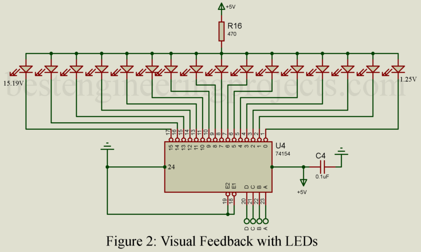
Want to see what’s happening without needing a multimeter? LEDs are wired to show the status of each relay. You can also use a 74LS154 decoder if you want to get fancy with a 16-step display. The decoder takes the binary output from the 4029 and translates it to a single LED, giving you a clear view of the current step. Think of it as a dashboard that tells you exactly which step your circuit’s on.
Step-by-Step Assembly
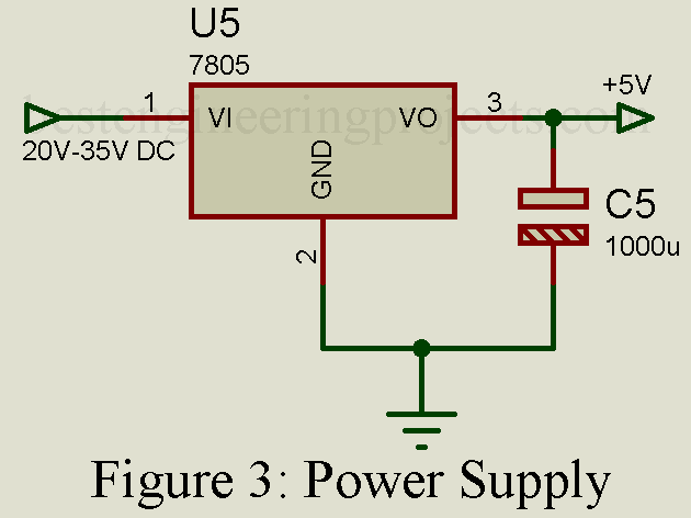
- Build the Power Section: Connect the LM317 with the input voltage (20V-35V) and set up the resistors. Attach the output side where it’ll feed into the relay network.
- Set Up the Counter and Clock: Use the 4093 IC to create the logic for S1 and S2. These buttons control the counter direction. Adjust VR1 to tweak the clock speed, which controls how fast the voltage steps change.
- Relay Control: Wire the 4029 counter’s binary outputs to transistors connected to each relay. As the count changes, different relays will turn on or off, changing the resistance in the circuit.
- Connect the LEDs: Wire LEDs for each relay to visually track which ones are active. This makes it easy to see the binary state directly.
- Test and Adjust: Once assembled, power it up and test by pressing S1 and S2 to increase or decrease the output voltage. Use VR2 to fine-tune the upper voltage limit if needed.
Real-Life Example
Let’s say you’re working on a delicate electronics project that needs exactly 5V, and you want to step up from a base voltage of 1.25V in small increments. Now switch on the supply, flick switch SW1 a few times, watching the LEDs light in turn, as the voltage steps up a little at a time. Before you know it you are right on 5V. Good.
Now, to drop back down again, just tap switch SW2 and watch the voltage decrease in steps but in a nice, polite manner. It’s a controlled dance, moving you up and down the voltage ladder.
Final Thoughts
Beneath the voltage regulator lies a lesson in digital logic, a session of practical electronics. For the hobbyist determined to get a project ‘just right’, or for an engineer that needs precision, a DIY variable power supply is a great thing to have on the bench.
Once you’ve built it, you’ll have not only one of the most useful, versatile, variable power supplies, but also an insight into exactly how digital counters and relays work together. And that’s knowledge applicable to so many other projects.
And now, go build! And, like with any recipe, follow the steps, experiment, and above all, enjoy the cooking.


