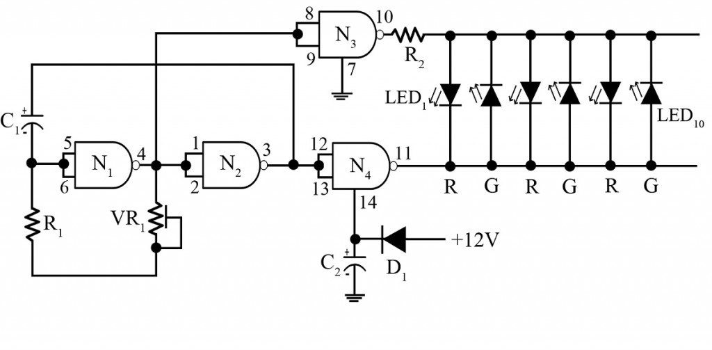
Blinking and shimmering of lights in disco keep everyone amazed, the entire design cost of which might seem high. A circuit is presented hereby is of disco light making use of low-cost CMOS chip CD4011B, which is a two-input quad NAND gate. Along with two particular gates; G1 and G2 as shown in the figure below, it works as an RC oscillator forming clock oscillator gates.
Circuit Description of Disco Light Circuit
Here the two input terminals of the CMOS chip are coupled together to form an inverter. And, again it is so adjusted that this particular IC starts working as an amplifier. The combination of VR1 (220KΩ) preset and R1 (10KΩ) resistor, supplies a negative DC feedback which biases the inverter just formed, in linear region to labor as an amplifier. The capacitor C1 in the figure is responsible to provide output for gate G2 and thus supplies positive feedback to make oscillation possible. The period of oscillation is strictly dependent on the values of R1, VR1, and C1.
Additional gates G3 and G4 are used as barriers between load and components that determine the frequency. And on the other hand, LEDs are adjusted to generate disco lights. These LEDs are placed in alternate positions on alternate cycles (you can get a clear view in the figure).
The use of low-cost components is the attractive feature of this project. To add more, the frequency of clock pulse in this circuit is adjustable for both LEDs and bi-color LEDs.
Check out other LED projects posted on bestengineeringprojects.com
- LED Matrix Display using Arduino
- LED Cube 4x4x4 Circuit using AT89C2051
- DIY Light Detector Circuit using LED
- Sound Level Meter Circuit
- LED Running Light Circuit
PARTS LIST OF DISCO LIGHT CIRCUIT
| Resistor (all ¼-watt, ± 5% Carbon) |
| R1 = 10 KΩ
R2 = 100 Ω/0.5W VR1 = 220 KΩ |
| Capacitors |
| C1 = 10 µF, 25V (Electrolytic Capacitor)
C2 = 150 µF, 63V (Electrolytic Capacitor) |
| Semiconductors |
| IC1 = CD4011B (two-input quad NAND gate IC)
D1 = 1N4001 (Rectifier Diode) LEDs |
