In this article we will analysis different type of D Type Flip Flip IC like dual type and quad type, it’s key parameter, applications and comment.
Dual Type D Flip Flop
Description
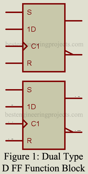
This universally used flip-flop (FF) contains two separate type D FFs, as illustrated in the functional diagram of figure 1. Each of the two FFs is identical and can be used separately or interconnected with each other for whatever purpose may be required. They can be used as shift register elements or as type D FFs for counter or toggle applications.
Key parameters of Dual Type D Flip Flip
- Quiescent current: The current drawn by the IC when no operations take place. 2.0 nA are typical at 5V for low-power CMOS.
- Toggle rate: The frequency with which the FF can change state. 4.0 MHz is typical for low-power CMOS and up to 50 MHz is typical for low-power TTL ICs.
- Propagation delay, clock to output: The time required from the clock pulse transition until a change occurs in the output terminal. 175 ns is typical for low-power CMOS and 10 ns is typical for low-power TTL ICs.
- Propagation delay, set or reset to output: The time required for either the set or reset signal to change the output. 175 ns is typical for low-power CMOS and 13 ns is typical for low-power TTL ICs.
- Clock pulse width: 250 ns is typical for low-power CMOS and 12 ns is typical for low-power TTL ICs.
Representative Part Number: Texas Instruments SN7474
Quad-Type D Flip Flip
Description
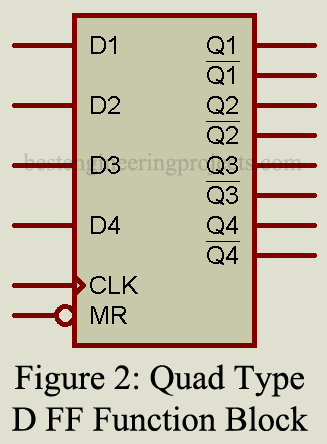
In this IC, four identical FFs are controlled by a common clock and reset signal, as illustrated in the logic diagram of figure 2. Note that the data input to each FF and both Q and outputs is buffered by separated amplifiers. Only during the positive going clock signal can the data present at the D-inputs be transferred to the Q outputs. The reset operation is possible at any time and is independent of the clock.
Key Parameters of Quad Type D Flip Flip
- Quiescent current: The current drawn by the IC when no operations take place. 5 nA is typical at 5V for low-power CMOS.
- Toggle rate: The highest frequency at which the FFs can change state. 4.5 MHz is typical for low-power and 45 MHz is typical for TTL ICs.
- Propagation delay, clock to output: The time from the clock pulse transition until a change occurs in the output. 220 ns is typical for low-power CMOS and 15 ns is typical for low-power TTL ICs.
- Propagation delay, reset to output: The time required after the application of the reset signal until the output is reset. 325 ns is typical for low-power CMOS and 40 ns is typical for low power TTL ICs.
- Clock pulse width: 110 ns is typical for low power CMOS and 20 ns is typical for low power TTL ICs.
Applications
These ICs can be connected as shift registers or counter elements as well as for specialized switching and timing control circuits.
Representative Part Number: Texas instrument SN74173
Comments
While the IC described here contains four FFs with common clock and reset, other ICs containing up to 16 FFs are available.

