Bipolar Digital to Analog Converter (DAC)
Digital to Analog converter is an important part of many system. In this section, we have taught what bipolar digital to analog converter are and for better explanation we had also includes various circuit diagram.
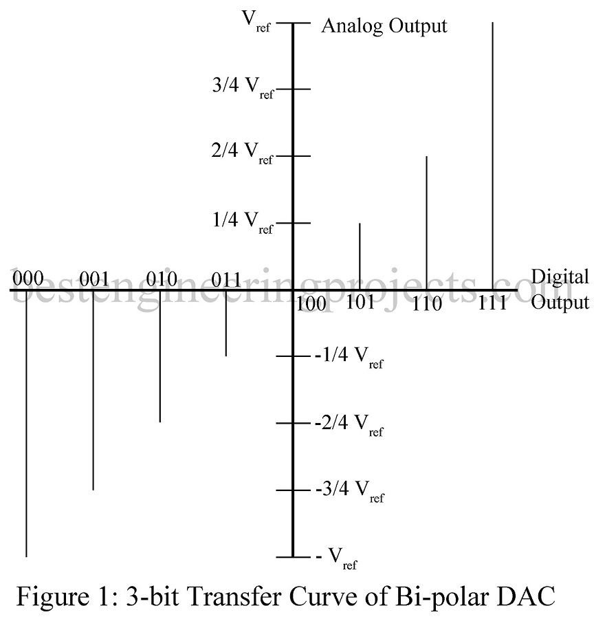
Normal (unipolar) digital to analog converter can only give output either of positive types or of negative types but bi-polar converter is used to achieve both positive and negative output. Figure 1 represent the transfer curve of bipolar digital to analog converter.

Working of Bipolar Digital to Analog Converter (DAC)
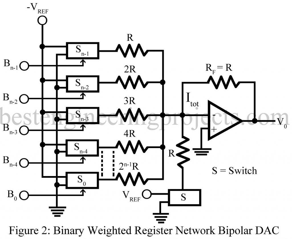
The circuit diagram of N-bit Bipolar Digital to Analog converter is shown in figure 2 and consist of n+1 number of switch and n number resistor where value of resistor is multiplying of R value.
- When switch S is at position low it behaves like open as a result the circuit is exactly the unipolar binary weighted resistor network DAC.
- If the switch S is at position high, the output voltage range for -Vref to +Vref (approximation) and hence, the circuit is called bipolar digital to analog converter.
Expression of output voltage of bipolar DAC: –
Therefore,
Where, D is decimal equivalent of binary input data.
When Rf = R, then,
For better understanding we had divided the expression into three cases
Case: 1
When all inputs bits are 0 i.e. D = 0
Therefore, V0 = -Vref
Case: 2
When only MSB = 1 rest all other bits are zero (0),
Therefore,
Case: 3
When all inputs bits are high i.e. 1
Therefore,
Conclusion
000 . . . . 000 represents -Vref
100 . . . . 000 represents 0V
111 . . . . 111 represents +Vref
