PH is a scale with which we can determine whether the water-based solution is acidic or basic. PH is represented as the power of hydrogen or the potential of hydrogen (Source: Wikipedia). With the help of electrodes, we can measure PH of solution electronically which could be more beneficial to measure and automate PH of the aquarium, or hydroponic or aquaponic. So, in this article, we will learn How to make Arduino PH Meter.
After completing this video one can
- Know about electrode and their working method
- Calibrate the module
- Measure PH of water-based solution using Arduino
- Measure temperature of solution and environment
Applications of Arduino PH Meter
- Automation of aquaponic, hydroponic, or even aquarium.
- Most plants require acidic PH to break down the mineral for proper growth with the help of this meter one can measure the PH of water and can select appropriate water.
- Most freshwater aquarium fish require PH of 6.8 to 7.6 for do best.
What is PH Electrode?
PH electrode is a device containing two different sensors (electrode), where the main sensor is made from PH glass which detects the presence of hydrogen ion and reference sensor usually made from silver or silver chloride.
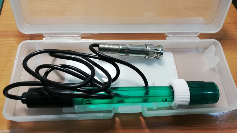 Figure: PH Electrode for Arduino
When the PH electrode is merged into liquid or solution, it generates a voltage according to the value of PH. The relation of output voltage and PH value is inverse i.e. at low PH value (acidic solution) it generates high voltage and as PH increases the output voltage starts to fall.
Let’s see the PH of daily uses substance
| Table 1: PH of Daily Uses Substance | |
| Substance | PH Range |
| Lemon Juice | 2.2 to 2.6 |
| Vinegar | 2.5 to 2.9 |
| Apple Juice | 3.5 |
| Coffee | 5.0 to 5.5 |
| Milk | 6.5 |
| Water | 7.0 |
| Seawater | 8.0 |
| Soap | 9.0 to 10.0 |
| Bleach | 13.0 |
Working on the PH Module Logo-Rnaenaor V2.0
The output voltage of the electrode is not enough that any microcontroller or Arduino can read. This voltage either needs amplification or we have to use high-bit ADC. This module amplifies this electrode voltage that Arduino can easily read without much error. The module is ideal for general-purpose lab professionals and field use. Now, let’s see the features of this module.
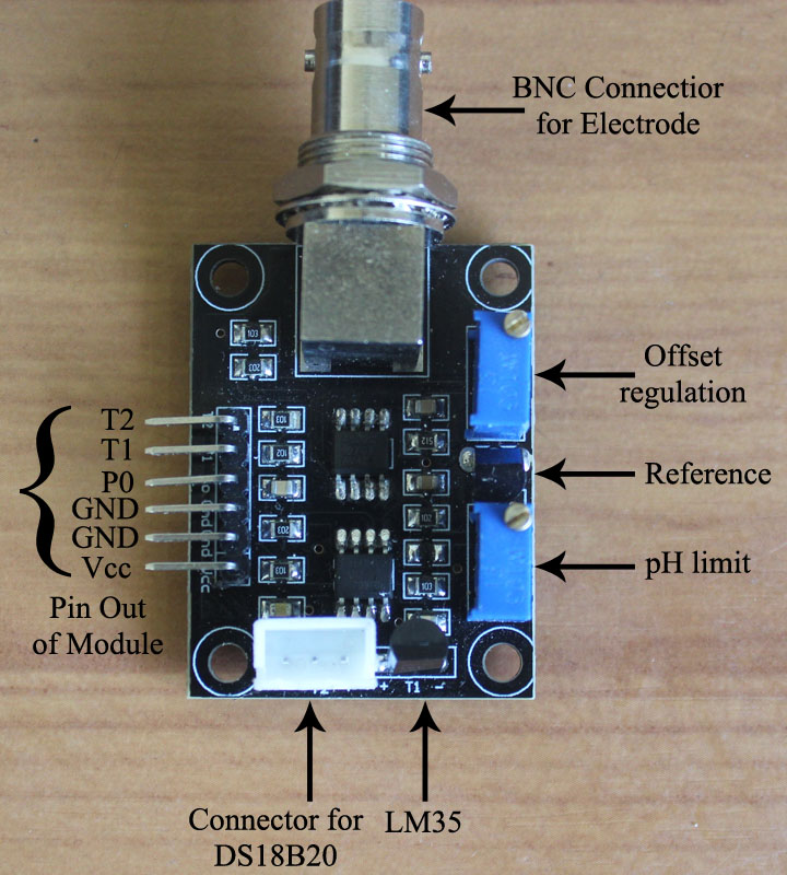 Figure 1: PH Module Logo-Rnaenaor V2.0
Feature of this board
- On-board temperature sensor (LM35) with which we can measure environment temperature.
- Dedicated connector for DS18B20 waterproof sensor so that we can measure the temperature of a water-based solution.
- BNC connector for PH electrode hence, easy to connect and disconnect.
- For minimal power loss and energy conservation, a P & N-channel D-S MOSFET is used.
- Precision programmable reference is used instead of a passive voltage divider for providing stable reference voltage.
- Two dedicated potentiometers, one for offset regulation with other for PH limit.
Pin Description of Module
Vcc = Positive Power supply pin
GND = Power supply Ground
GND = Analog Sensor GND
P0 = PH output pin (Analog Pin)
T1 = Output pin of onboard temp. sensor LM35 (Analog Pin)
T2 = Output pin of DS18B20 waterproof temp. sensor (Digital Pin)
Circuit Description of Arduino PH Meter
The circuit of the Arduino PH meter is shown in figure 1. +5V from Arduino is connected to Vcc of the module where GND pin to GND. The output of Electrode and temperature sensor T1 (LM35) is analog, the P0 pin represents the output of the electrode and the T1 represents the output pin of LM35. Check out the article on interfacing LM35 with Arduino. These two pins are connected to the analog pin of Arduino.
You can use any analog pin except A4 and A5 because here we are using the I2C protocol for LCD. For instance, P0 is connected to A0, and T1 is connected to A1. Pin T2 of the module is DQ (output of DS18B20) is digital. Thus, pin T2 is connected digital D5 pin as shown in the circuit diagram. An electrode is connected to BNC connected to where DS18B20 is connected to the connector. VCC and GND of DS18B20 are connected to + and – pin marked near connector where DQ pin is connected to the middle pin of the connector. Check out the tutorial on how to interface DS18B20 with Arduino.
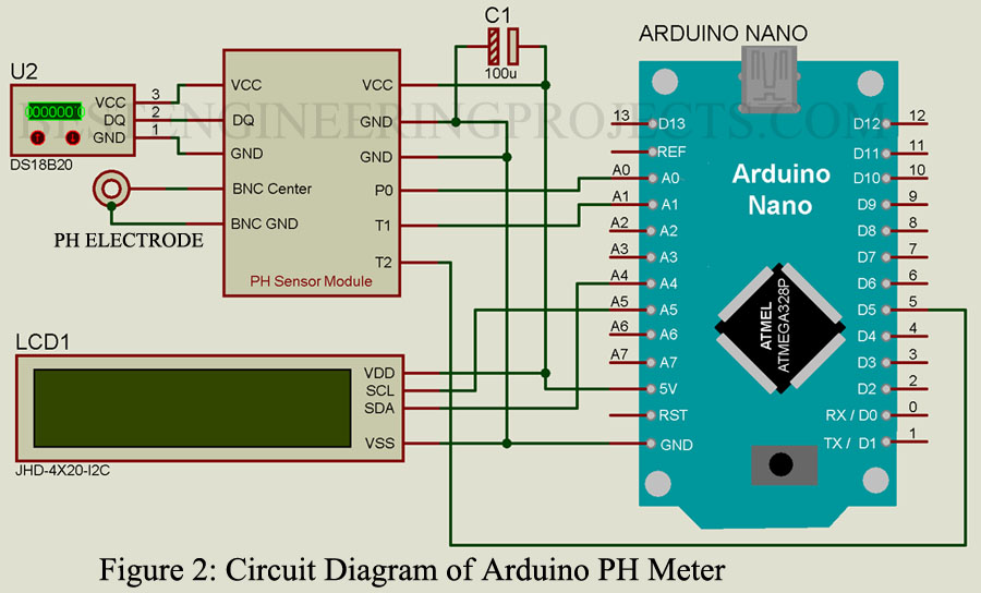
LCD is connected to Arduino in I2C protocol i.e. SDA and SCL pin of LCD is connected to SDA (A4) and SCL (A5) of Arduino respectively. For better power regulation a capacitor of 100uF is connected across Arduino 5V pin and GND pin as shown in the circuit diagram.
According to the manufacture datasheet at PH 7, it produces zero potential. For acidic solution, it produces positive potential and for a basic solution, it produces negative potential. As Arduino cannot read negative potential directly so we need proper calibration. We have to change negative potential to positive potential. So, we make PH 7.0 solution as middle point let say 2.5V i.e. when we immerse the electrode in pure water it will display 2.5V.
Calibration of PH Meter
Step 1: Connect the circuit as shown in the circuit diagram.
Step 2: Upload the program given below to your Arduino board. (This program is only for voltage reading, if you wish to measure potential at pin P0 using a multimeter then this step is not compulsory).
|
1 2 3 4 5 6 7 8 9 10 11 12 13 14 15 16 17 18 19 20 21 |
#include <LiquidCrystal_I2C.h> //Library for I2C lcd LiquidCrystal_I2C lcd(0x27,20,4); void setup() { lcd.init(); //initialization the lcd lcd.backlight(); } // the loop routine runs over and over again forever: void loop() { int sensorValue = analogRead(A0); // Convert the analog reading (which goes from 0 - 1023) to a voltage (0 - 5V): float voltage = sensorValue * (5.0 / 1023.0); // print out the value you read: lcd.setCursor(0,0); lcd.print("3.04"); lcd.setCursor(4,0); lcd.print("V"); delay(500); } |
Step 3: Remove the electrode from the BNC connector and short the inside connector with an outside connector of BNC. i.e. positive and negative pin of the BNC connector is short-circuited.
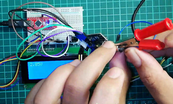 Figure 3: Sorting of BNC Connector
Step 4: Adjust the offset calibration potentiometer (closer to the BNC connector) until 2.5V is obtained.
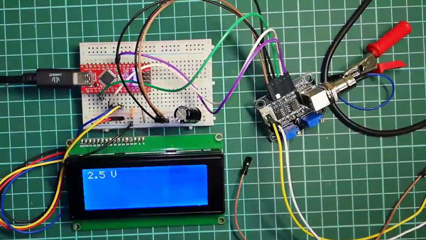 Figure 4: Voltage at Sorted BNC Connector
Step 3: Similarly, immerse the electrode in PH 6.86 (under the temperature of 250C) standard buffer solution of phosphate, and gently shake it, and note down the corresponding voltage.
Step 4: Again, immerse the electrode in pH4.01 or pH9.18 the standard buffer solution of borax, and note down the corresponding voltage.
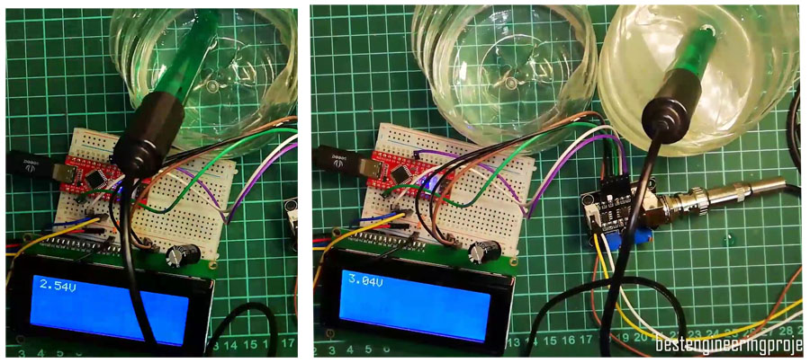 Figure 5: Voltage at different solution
Mathematics Calculation required
The voltage read by Arduino is now converted to PH by using the equation of straight link i.e. Y = mX + C. For converting we need slope (m) and constant (C). For calculating m and C we had taken the voltage reading at two different pH solutions.
While testing in Best Engineering Projects Lab we found corresponding reading
Voltage at pH 6.86 = 2.54V
Voltage at pH 4.01 = 3.04V
Formula for slope:  .
.
Let, X parameter be voltage and the Y parameter be PH value.
Thus, X2 = 3.04, X1 = 2.54V, Y2 = 4.01, Y1 = 6.86
Now putting these values in equation

Therefore, m = -5.7
Now, putting the value of slope (m) in equation Y = mX + C with the value of X = 2.54 and Y = 6.86.
C = Y – mX = 6.86 – (-5.7) x 2.54
Therefore, C = 21.34
These are the value we need in our software code for calculation the PH value of the water-based solutions.
Software Code for Arduino PH Meter
Software is written in Arduino programming language and compiled using Arduino IDE. This software takes reading from the electrode, LM35, and DS18B20 and converts it into the PH of the solution, surrounding temperature, and solution temperature. For working on this software code, we need four libraries. LiquidCrystal_I2C for I2C 20×4 LCD, one wire, and DallasTemperature for DS18B20 waterproof temperature sensor and math.h is used to calculate the absolute value of float type quantity for calibration. In software code, we had also generated a special character for  . This software code takes 10 different readings at a fixed interval of time and calculates the average. This average value is further converted to voltage and then PH using the formula of a straight line. Later we compare the temperature of the surrounding and solution and further calibrate the PH value.
 Figure 6: Author Prototype of Arduino PP Meter
Note: #include <math.h> is not necessary as it already includes by default but here for demo (working of fabs) we are including. So, using and not using this library won’t affect the code.
|
1 2 3 4 5 6 7 8 9 10 11 12 13 14 15 16 17 18 19 20 21 22 23 24 25 26 27 28 29 30 31 32 33 34 35 36 37 38 39 40 41 42 43 44 45 46 47 48 49 50 51 52 53 54 55 56 57 58 59 60 61 62 63 64 65 66 67 68 69 70 71 72 73 74 75 76 77 78 79 80 81 82 83 84 85 86 87 88 89 90 91 92 93 94 95 96 97 98 99 100 101 102 103 104 105 106 107 108 109 110 111 112 113 114 115 116 |
//Header declearation Start #include <LiquidCrystal_I2C.h> //Library for I2C lcd #include <OneWire.h> //One wire library #include <DallasTemperature.h> //Library for DS18B20 Sensor #include <math.h>// Library for math function //Header Declearation End //Pin Assignment and declearation Start #define ONE_WIRE_BUS 5 //data pin DQ pin of DS18B20 connected to digital pin D5 LiquidCrystal_I2C lcd(0x27,20,4); //set the LCD address to 0x27 for a 20 chars and 4 line display const int analogPhPin = A0; //PH module pin P0 connected to analog pin A0 const int analogTemPin = A2; //PH module pin T1 connected to analog pin A1 OneWire oneWire(ONE_WIRE_BUS); //Ste up one wire instance DallasTemperature sensors(&oneWire); //pass one wire reference to DS18B20 library long phTot, temTot; float phAvg, temAvg; int x; const float C = 21.34; //Constant of straight line (Y = mx + C) const float m = -5.70; // Slope of straight line (Y = mx + C) //Pin Assignment and declearation end // start for generate custom character byte customChar[] = { B00100, B00100, B11111, B00100, B00100, B00000, B11111, B00000 }; //End for generate custom character //Setup Function Start void setup() { lcd.init(); //initialization the lcd lcd.backlight(); sensors.begin(); //Start the DS18B20 Library lcd.setCursor(0,0); lcd.print("PH and Temperature"); lcd.setCursor(0,1); lcd.print("Meter Using"); lcd.setCursor(0, 2); lcd.print("Arduino"); delay(3000); lcd.clear(); } //Setup Function End //Main function Start void loop() { phTot = 0; temTot = 0; phAvg = 0; temAvg = 0; //taking 10 sample and adding with 10 milli second delay for(x=0; x<10 ; x++) { phTot += analogRead(A0); temTot += analogRead(A1); delay(10); } float temAvg = temTot/10; float phAvg = phTot/10; float temVoltage = temAvg * (5000.0 / 1023.0); //convert sensor reading into milli volt float phVoltage = phAvg * (5.0 / 1023.0); //convert sensor reading into milli volt sensors.requestTemperatures(); // Send the command to get temperatures float Etemp = temVoltage*0.1; //convert milli volt to temperature degree Celsius float pHValue = phVoltage*m+C; float Wtemp = sensors.getTempCByIndex(0); float TempDif = fabs(Etemp-Wtemp); //calculating the absolute value of floating // lcd.clear(); lcd.setCursor(0,0); lcd.print("Env.Tmp."); lcd.setCursor(12,0); lcd.print("Sol.Tmp."); lcd.setCursor(1,1); lcd.print(Etemp); lcd.setCursor(6,1); lcd.write(B11011111); lcd.setCursor(7,1); lcd.print("C"); lcd.setCursor(13,1); lcd.print(Wtemp); lcd.setCursor(18,1); lcd.write(B11011111); lcd.setCursor(19,1); lcd.print("C"); lcd.setCursor(0,2); lcd.print("PH Value of Solution"); lcd.setCursor(3,3); lcd.print(pHValue); lcd.setCursor(9,3); lcd.print("PH"); if (TempDif<= 5) { lcd.setCursor(11,3); lcd.write(customChar); lcd.setCursor(14,3); lcd.print("0.1PH"); } if (TempDif> 5) { lcd.setCursor(11,3); lcd.write(customChar); lcd.setCursor(14,3); lcd.print("0.2PH"); } delay(1000); } |
Making Video Part 1:
Hi,
I am working with this sensor but am not able to calibrate to 2.5V as mentioned in steps 3 and 4. The lowest voltage I can achieve is 2.6V. When no probe is connected, the voltage is ~0.7V and can vary up to 2V, but is inconsistent. The LM35 temperature reading is also very inconsistent, and is reading high.
Wondering if you have any suggestions?
As maximum voltage that arduino can measure is 5V, so i had calibrate to 2.5V.
If the voltage is less then 2.5V then the solution is basic and if the voltage is greater then 2.5V then the solution is acidic.
You can use that voltage (2.6V) in calculation instead of 2.5V.
For stable reading of LM35 please go through the article:
LM35: How to get stable temperature reading
Thanks for the response. I’ll give your suggestions a try.
error in line 68 – float phAvg = temTot/10;
Should be written- float phAvg = phTot/10;
Thank you, we had updated the code.
How many trials needs to be done about accuracy testing of pH level sensor?