A decibel meter is an instrument to measure levels of the input signal(s) in decibel units. The main areas of application of decibel meter are audio level indicators, record level indicators, spectrum analyzers, and the like. The project “A versatile decibel meter circuit” shows here provides a resolution of 20 steps. Although the steps are linear, they are calibrated with corresponding decibel value so that it suits most of the requirement.
Description of Versatile Decibel Meter Circuit
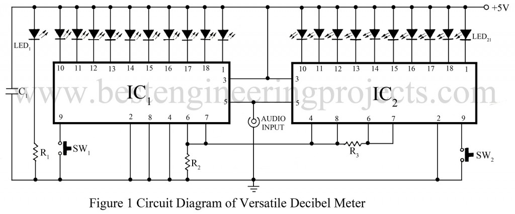
The schematic diagram of the versatile decibel meter circuit is shown in figure 1 is based on op-amp IC LM3914 for bar graph generating. LM3914 has 11 op-amps, out of which one is used as buffering and the rest areas comparators. The output of the buffer amplifier is linked with the entire inverting input of comparators, where non-inverting inputs are used for different reference voltage generated by the resistor ladder.
Check out other sound or volume indicator circuits posted in bestengineeringprojects.com
- Sound Level Meter Circuit using Arduino
- Sound Level Meter Circuit
- Sound VU Meter Using Arduino
- VU Meter Circuit using ATmega32
At pin 4 and 6 of LM3914, these ladders are available externally. The reference preset input at pin 8 is used to elevate the output of reference voltage at pin 7, which incorporates a stable reference voltage. The current at the outputs can be determined by the load resistor connected to pin 7 and ground when outputs are active low. The appropriate logic at pin 9 of LM3914 selects the mood of operation from two modes – bar mode and dot mood.
LM3914 has 10 outputs so; in order to obtain 20 steps, two ICs are used. Pin 4 of IC1 is grounded so that the lowest levels of input signals are detected linearly. The reference voltage of 1.25V from pin 7 is given to pin 6. So each comparator switches at steps of 0.125V of the input signal. The load resistor R2 and R3 limit the current through each LED to 12 mA.
The reference voltage of IC2 is made at 2.5V by raising pin 8 to 1.25V obtained from pin 7 of IC1. The divider’s lower end is also raised to 1.25V so that signals above 1.25V are handled by IC2. The voltage at pin 7 of IC2 is now 2.5V and is given to pin 6 of IC2 to fix the divider’s higher end of IC2 to 2.5V.
The entire circuit has 20 comparators, each with a reference voltage of 0.125V. The output can be selected to bar or dot mode by applying high or low logic respectively to pin 9.
The circuit can be used for any range. The range can be obtained by attenuating the input signal accordingly. Otherwise, a multi-way switch can be used to select the range which switches over to different potentiometers that were preset for different ranges.
Decibel values related to some parameters are given by power in dB = 1- log (P2/P1)
Where P2 is power in question and p1 is the power to which P2 is referred to Voltage in dB = 20 logs (V2/V1)
Where V2 is power in question and V1 is the power to which V2 is referred.
The most cases, a power of 1 mW dissipates in a 600 ohms resistor is taken as reference. That corresponds to a voltage level of 0.7745 volts. This means that 0.7745 volts are taken as 0 dB. As such, the sixth LED corresponds to 0 dB in this circuit. The decibel values for other LEDs can be calculated by the formula
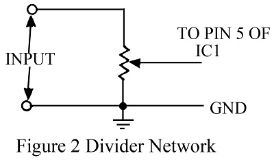
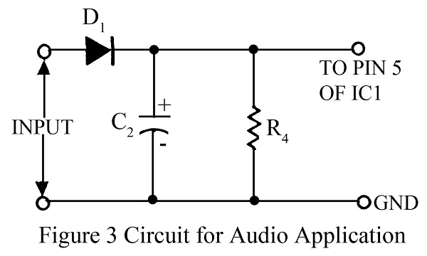
Where n is the number of the particular LED. To change the above values to suit someone’s replacement, divide the incoming voltage through a potentiometer as shown in figure 2. The choice of VR1 depends upon the input impedance required.
PARTS LIST OF VERSATILE DECIBEL METER CIRCUIT
|
Resistors (all ¼-watt, ± 5% Carbon) |
|
R1 = 390 Ω R2, R3 = 1.5 KΩ R4 = 27 KΩ |
|
Capacitors |
|
C1 = 0.1 µF (Ceramic Disc) C2 = 10 µF/25V (Electrolytic Capacitor) |
|
Semiconductors |
|
IC1, IC2 = LM3914 (Dot/Bar Display Driver) D1 = 1N4148 (Silicon Signal Switching Diode) LED1 – LED21 = Indicator |
|
Miscellaneous |
|
SW1, SW2 = Push-to-on Switch |


