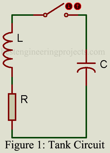
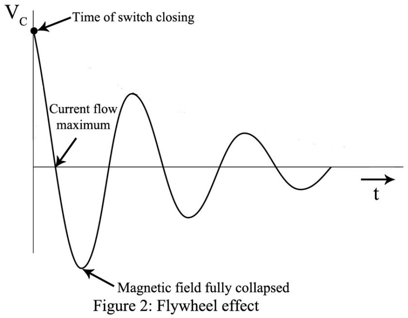
Working of LC Oscillator: The effect of charging the capacitor in Fig. 1 to some voltage potential and then closing the switch results in the waveform shown in Fig. 1. The switch closure starts a current flow as the capacitor begins to discharge through the inductor. The inductor, which resists a change in current flow, causes a gradual sinusoidal current buildup that reaches the maximum when the capacitor is fully discharged. At this point, the potential energy is zero, but since the current flow is maximum, the magnetic field energy around the inductor is maximum.
The magnetic field no longer maintained by capacitor voltage then starts to collapse, and its counter EMF will keep current flowing in the same direction, thus charging the capacitor to the opposite polarity of its original charge. This repetitive exchange of energy is known as the flywheel effect. The circuit losses (mainly the dc winding resistance of the coil) cause the output to become gradually smaller as this process repeats itself after the complete collapse of the magnetic field. The resulting waveform, shown in Fig. 2, is termed a damped sine wave. The energy of the magnetic field has been converted into the energy of the capacitor’s electric field, and vice versa.
The process repeats itself at the natural or resonant frequency, fr, as predicted by Eq. 1:
…..(1)
This is the frequency of the LC oscillator.
For an LC tank circuit to function as an oscillator, an amplifier is utilized to restore the lost energy to provide a constant-amplitude sine-wave output. The resulting “undamped” waveform is known as a continuous wave (CW) in radio work. The most straightforward method of restoring this lost energy is now examined, and the general conditions required for oscillation are introduced.
The LC oscillators are feedback amplifiers, with the feedback serving to increase or sustain the self-generated output. This is called positive feedback, and it occurs when the fed-back signal is in phase with (reinforces) the input signal. It would seem, then, that the regenerative effects of this positive feedback would cause the output to increase continually with each cycle of the fed-back signal. However, in practice, component nonlinearity and power supply limitations limit the theoretically infinite gain.
The criteria for oscillation are formally stated by the Barkhausen criteria as follows:
- The loop gain must equal 1.
- The loop phase shift must be n x 360°, where n = 1,2,3,
An oscillating amplifier adjusts itself to meet both of these criteria. The initial surge of dc power or noise in the circuit creates a sinusoidal voltage in the tank circuit at its resonant frequency, and it is fed back to the input and amplified repeatedly until the amplifier works into the saturation and cutoff regions. At this time, the flywheel effect of the tank is effective in maintaining a sinusoidal output. This process shows us that too much gain would cause excessive distortion and therefore the gain should be limited to a level that is just greater than or equal to 1.

