What is Cavity Resonator? Circuits composed of lumped inductance and capacitance elements may be made to resonate at any frequency from less than 1 Hz to many thousand megahertz. At extremely high frequencies, however, the physical size of the inductors and capacitors becomes extremely small. Also, losses in the circuit become extremely great. Resonant devices of different construction are therefore preferred at extremely high frequencies. In the UHF range, sections of parallel wire or coaxial transmission lines are commonly employed in place of lumped constant resonant circuits. In the microwave region, cavity resonators are used. Cavity resonators are metal-walled chambers fitted with devices for admitting and extracting electromagnetic energy. The Q of these devices may be much greater than that of conventional LC tank circuits.
Although cavity resonators, built for different frequency ranges and applications, have a variety of physical forms, the basic principles of operation are essentially the same for all. The operating principles of cavity resonators are explained here.
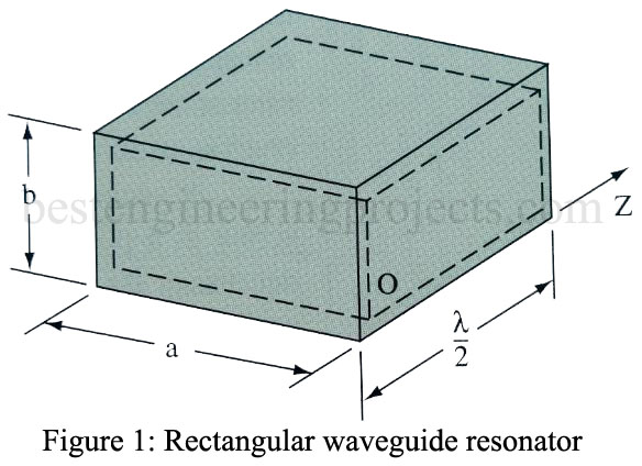
Resonant cavity walls are made of highly conductive material and enclose a good dielectric, usually air. One example of a cavity resonator is the rectangular box shown in Figure 1. It may be thought of as a section of rectangular waveguide closed at both ends by conducting plates. Because the endplates are short circuits for waves traveling in the Z direction, the cavity is analogous to a transmission line section with short circuits at both ends. Resonant modes occur at frequencies for which the distance between end plates is a half wavelength or multiple of a half wavelength.
Cavity modes are designated by the same numbering system that is used with waveguides, except that a third subscript is used to indicate the number of half-wave patterns of the transverse field along the axis of the cavity (perpendicular to the transverse field). The rectangular cavity is only one of many cavity devices useful as high-frequency resonators. By appropriate choice of cavity shape, advantages such as compactness, ease of tuning, simple mode spectrum, and high Q may be secured as required for special applications. Coupling energy to and from the cavity is accomplished just as for standard waveguide, as shown in Figure 2 of the previous article Coupling Waveguide Energy.
Cavity Tuning
The resonant frequency of a cavity may be varied by changing any of three parameters: cavity volume, cavity inductance, or cavity capacitance. Although the mechanical methods for tuning cavity resonators may vary, they all utilize the electrical principles explained below.
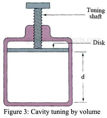
Figure 2 illustrates a method of tuning a cylindrical-type cavity by varying its volume. Varying the distance d will result in a new resonant frequency. Increasing distance d will lower the resonant frequency while decreasing d will cause an increase in resonant frequency. The movement of the disk may be calibrated in terms of frequency. A micrometer scale is usually used to indicate the position of the disk, and a calibration chart is used to determine the frequency.
A second method for tuning a cavity resonator is to insert a nonferrous metallic screw at a point of maximum H field. This decreases the permeability of the cavity and decreases its effective inductance, which raises its resonant frequency. The farther the screw penetrates into the cavity, the higher is the resonant frequency. A paddle can be used in place of the screw. Turning the paddle to a position more nearly perpendicular to the H field increases the resonant frequency.

