Waveguides are capable of propagating huge amounts of power. For example, typical X-band (0.9 x 0.4 in) waveguides can handle 1 million W if operated at 1.5 times fco, and an air dielectric strength of 3 x 10⁶ V/m is assumed. At frequencies below cutoff, the waveguide attenuation is very rapid. At frequencies above the cutoff, the guide supports traveling waves, and they are slightly attenuated because of losses in the conducting walls and in the dielectric that fills the guide. For air-filled guides, the dielectric loss is normally negligible, but if dielectric other than air is used, these losses are often greater than the conductor losses. As the frequency increases, waveguide attenuation drops to a broad minimum and then increases slowly with increasing frequency.
The conductor losses are governed in part by the skin effect. (At high frequencies the current tends to flow only at the surface of a conductor.) Current that flows in the guide walls are concentrated near the inner surface.
Bends and Twists | Waveguide Attenuation
It is often necessary to change the physical direction of propagation or the wave’s polarization in waveguides.
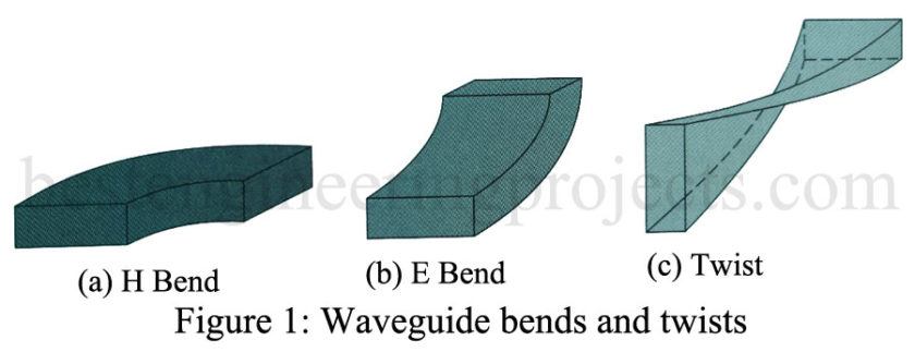
- H bend [Figure 1(a)]: It is used to change the physical direction of propagation. It derives its name from the fact that the H lines are bent in this transition, while the E lines remain vertical for the dominant model.
- E bend [Figure 1(b)]: This section is also used to change the physical direction of propagation. The choice between an E or H bend is normally governed by mechanical considerations (plumbing considerations if you will) since neither produces large discontinuities if the bends are gradual enough.
- Twist [Figure 1(c)]: A twist section is used to change the plane of polarization of the wave. It can be seen that any desired angular orientation of the wave may be obtained with an appropriate combination of the three types of sections just discussed.
Tuners
A metallic post inserted in the broad wall of a waveguide provides a lumped reactance at that point. The action is similar to the addition of a shorted stub along a transmission line. When the post extends less than a quarter wavelength it appears capacitive, while exceeding a quarter wavelength makes it appear inductive. Quarter-wavelength insertion causes a series resonance effect whose sharpness (Q) is inversely proportional to the diameter of the post.
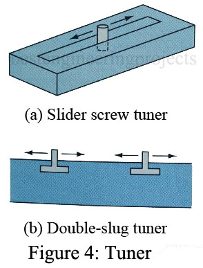
The primary usage of posts is in matching a load to a guide so as to minimize the VSWR. The most often used configurations are shown in Figure 4.
- Slide-screw tuner [Figure 4(a)]: The slide-screw tuner consists of a screw or metallic object of some sort protruding vertically into the guide and adjustable both longitudinally and in-depth. The effect of the protruding object is to produce shunting reactance across the guide—thus, it is analogous to a single-stub tuner in transmission line theory.
- Double-slug tuner [Figure 4(b)]: This type of tuner involves placing two metallic objects, called slugs, in the waveguide. The necessary two degrees of freedom to effect a match are obtained by making adjustable both the longitudinal position of the slugs and the spacing between them. Thus, it is somewhat analogous to the transmission line double-stub tuner but differs in that the position of the slugs and not the effective shunting reactance is variable.

