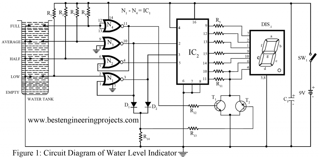
Normally we have seen on different websites, the overall circuit of the water level indicator uses a bar graph or a seven-segment display to indicate the water level. This type of representation using LEDs or digits for water level makes the observer which includes a large number of normal people, difficult to understand.
A consequence of using those methods makes the whole effort inadequate. The circuit presented below surmounts this flaw and displays the water level using a seven-segment display, but there is a difference. The water level indicator circuit displays the water level with distinct symbols(i.e. it uses meaningful English letters ) for each level. For example, to indicate an empty fluid level, it uses ‘E’. In similar ways, ‘L’ for low, ‘H’ for half, ‘A’ for average, and ‘F’ for a full tank. The water level indicator circuit is, therefore, can be considered more reliable and user-friendly.
Other Water level indicators and controller circuits are posted on bestengineeringprojects.com
Description of Water Level Indicator Circuit
Talking the construction of a water level indicator circuit, uses CMOS ICs. CD4001 (IC1) is a quad. NOR gate and CD4055 is a BCD to the seven-segment decoder and display driver IC. The decoder IC used in this circuit has the capability to produce some English alphabets in addition to the usual digits 0 to 9.

The BCD codes for different displays are demonstrated in Table I. as the sensing probes get immersed in water, with the interconnections of NOR gates, the BCD codes are generated.
The IC cannot provide display patterns for letters E and F. Therefore separate arrangements are made for them. For this purpose transistors, T1 and T2 are added to the water level indicator circuit. The transistors clear the unnecessary segments from the seven-segment display to produce the required symbol. In order to construct the letter E, segments ‘b’ and ‘c’ can be blanked out from the seven-segment display while it decodes digit 8. Similarly, the letter F can be obtained by clearing segment ‘b’ while it decodes the letter P.
There lies an extra advantage to the water level indicator circuit, as CMOS IC is used the current consumption by the overall circuit is extremely low. Therefore, the power required to operate the water level indicator circuit can be fed through a simple battery. With all four probes immersed in water, the input sensing current through the fluid is of the order of 70 µA. This prevents excessive damage to the probes used as it lowers the rate of deterioration due to oxidation and also a low level of electrolysis in the fluid.
The water level indicator circuit can also be used to indicate the fluid level in most cases, but it must not be used with inflammable or highly reactive fluids. The consequences can be adverse.
Indication of Water level Indicator Circuit
| Table 1 For Water Level Indicator Circuit | ||||
| D | C | B | A | DISPLAY |
| L | L | L | L | 0 |
| L | L | L | H | 1 |
| – | – | – | – | 2 |
| – | – | – | – | 3 |
| – | – | – | – | 4 |
| – | – | – | – | 5 |
| – | – | – | – | 6 |
| – | – | – | – | 7 |
| H | L | L | L | 8 |
| H | L | L | H | 9 |
| H | L | H | L | L |
| H | L | H | H | H |
| H | H | L | L | P |
| H | H | H | H | A |
| H | H | L | L | – |
| H | H | H | H | BLANK |
PARTS LIST OF WATER LEVEL INDICATOR CIRCUITS
| Resistor (all ¼-watt, ± 5% Carbon) |
| R1 – R4 = 470 KΩ
R5 – R11 = 680 Ω R12 – R13 = 10 K Ω R14 = 2.7 K Ω |
| Capacitor |
| C1 = 100 µF/16V (Electrolytic Capacitor) |
| Semiconductors |
| IC1= CD4001 (Quad Nor Gate)
IC2 = CD4055 (7-segment Decoder IC) T1 = BC148 (Silicon NPN Transistor) T2 = BC557 (PNP Transistor) D1 – D2 = 1N4148 (Switching Signal Diode) DIS1 = LTS543 (7-segment display) |
| Miscellaneous |
| SW1 = ON/OFF Switch
B1 = 9V battery Probe |
Hello , please am trying to simulate such project using proteus but am not getting the expecting outcome .
Hello , please am trying to simulate such project using proteus but am not getting the expecting outcome .Please how do I go by it