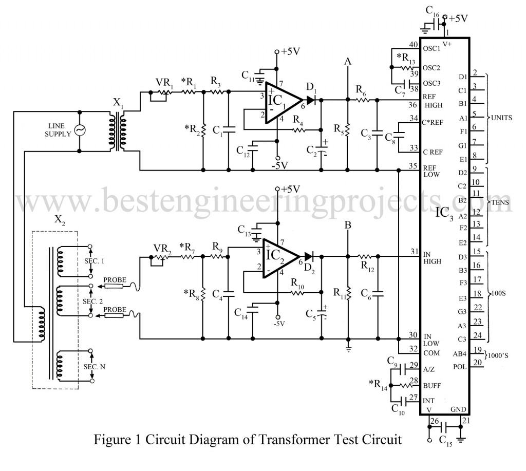
One of the initial production tests carried out on power transformers used in electronic equipment is the measurement of on-load voltages across their secondary windings. During this test, the basic requirement is that the voltage across the primary winding is maintained at the rated line voltage. But in practice, there will be variations in the line voltage and its effect will be reflected on the secondary side. Hence the test carried out will have their internal error.
Circuit Description of Transformer test circuit to overcome line voltage variation
Here is a simple test circuit “Transformer test circuit to overcome line voltage variation” shown in figure 1 offsets the effects of variations in the line voltage and reads the voltage across the winding corresponding to the rated line voltage applied to the primary winding. For example, a transformer having a secondary voltage of 12 volts for a primary voltage of 230 volts will produce a secondary voltage of 12.5 volts when the line voltage has varied to 240 volts. But this test circuit applies corrections and reads 12 volts. This is made possible by deriving a reference voltage in the circuit proportional to the line voltage.
Intersil IC 7107 (IC3), a high-performance 7/2-digit analog-to-digital converter is used to measure and display the rectified output of the secondary windings. The reference voltage, which establishes the full-scale value of the ADC, is made proportional to the line voltage. Transformer X1 senses the line voltage. Op-amps IC1 and IC2 are configured as precision peak-detector circuits. Preset VR1 is adjusted to get a reference voltage of 1.000V DC at peak-detector 1 output corresponding to the line voltage of 230V. Preset VR2 is adjusted to get a voltage of 2.000V at peak-detector 2 output for a voltage of 20 volts RMS across the input probes.
A number of transformers having different secondary voltages were tested using this tester. The supply voltage was varied from 180V to 250V AC and the display readings were found to be accurate to 0.5V percent.
Although the voltage divider consisting of VR2, R7, and R8 is designed for a measurement range of 20V AC, it can be suitably modified to measure higher voltages.
NOTE: Voltage at point A is Va (1.000V DC) at a line voltage of 230V AC.
The voltage at point B is Vb (2.000V DC) at 20V AC across the probe inputs.
PARTS LIST OF TRANSFORMER TEST CIRCUIT TO OVERCOME LINE VOLTAGE VARIATION
|
Resistors (all ¼-watt, ± 5% Carbon) |
|
R1, R7 = 12 KΩ 0.1% (Metal Film) R2, R8 = 1 KΩ 0.1% (Metal Film) R3, R4, R9, R10 = 10 KΩ R5, R11 = 100 KΩ R6, R12 = 1 MΩ R13 = 100 KΩ 0.1% (Metal Film) R14 = 470 KΩ 0.1% (Metal Film) VR1 = 2KΩ |
|
Capacitors |
|
C1, C3, C4, C6, C8 = 0.01 µF C2, C5 = 10 µF/10V C7 = 100 pF (Silver Mica) C9 = 0.047 µF C10 = 0.22 (Polypropylene Type) C11 – C16 = 0.1 µF |
|
Semiconductors |
|
IC1, IC2 = OP07 IC3 = L7107 D1, D2 = 1N4148 |
|
Miscellaneous |
|
X1 = Sense Transformer 230V AC Primary to 0-10V Secondary X2 = Transformer Unser Test |
