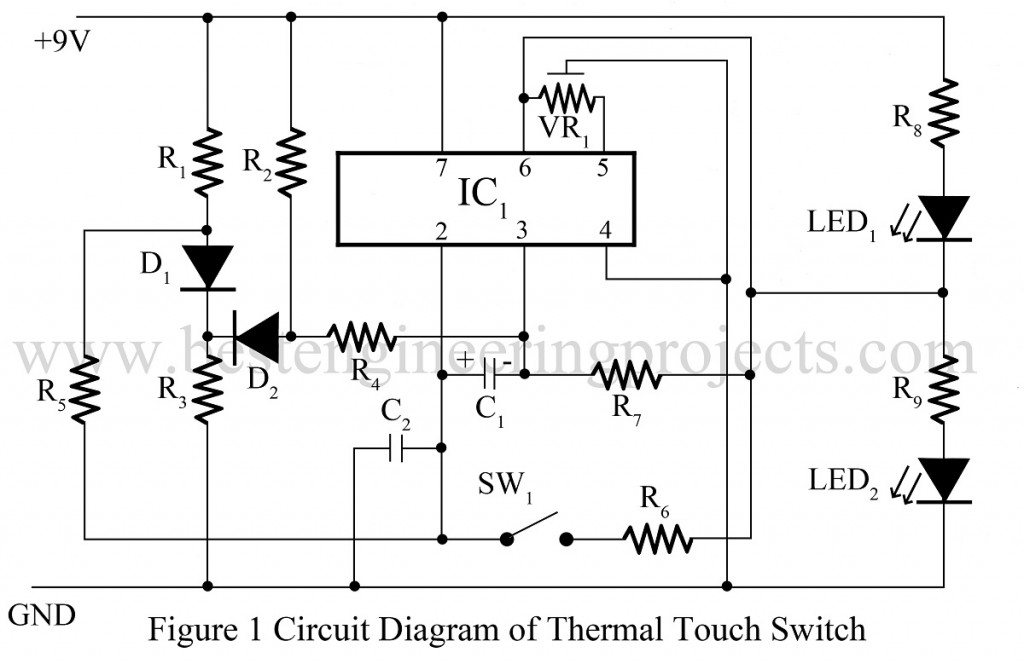
Various types of switch circuits like a light operated switch, sound operated switch, etc is already posted on www.bestengineeringprojects.com. Now here is a thermal touch switch that automatic on and off due to the increase and decrease of pre-defined temperature. This type of circuit is useful to operate fans, cooler, etc.
Circuit description of thermal touch switch using operational amplifier 741
The circuit comprises an operational amplifier IC (IC1), silicon diode (D1 and D2), and a few passive components to complete the circuit. Diode D1 is used here as a temperature sensor. OP-amp 741 is used here as a comparator.
When the temperature is low, diode D1 does not connect and the output of IC1 is low when the temperature increases D1 starts conducting and the output of IC1 is high, which further glow LED LED2.
For adjustment of pre-define temperature put switch SW1 on and adjust potentiometer VR1 so that output at pin 6 is half of the supply voltage.
NOTE: To control appliance according to temperature use relay with driver circuit at output pin 6.
Check out other touch-operated switches posted in bestengineeringprojects.com
- Touch Switch Circuit using Transistor
- Touch Switch-Cum-Heat Operated Switch
- Clap Switch Cum Touch Switch
- Thermal Touch Switch using op-amp 741
- Simple Touch Switch Using Two Transistors
PARTS LIST OF THERMAL TOUCH SWITCH USING OPERATIONAL AMPLIFIER 741
|
Resistor (all ¼-watt, ± 5% Carbon) |
|
R1, R2 = 10 KΩ R3 = 4.7 KΩ R4, R5 = 1 KΩ R6 = 1 MΩ R7 = 10 MΩ R8, R9 = 470Ω VR1 = 10 KΩ |
|
Capacitors |
|
C1 = 100 µF, 10V (Electrolytic Capacitor) C2 = 10 KpF (Ceramic Disc) |
|
Semiconductors |
|
IC1 = LM741 (Operational Amplifier) D1, D2 = 1N4148 (Small Signal Diode) |
|
Miscellaneous |
|
SW1 = On/off Switch LED1, LED2 |

how can this circuit be tested
what will be the changes in this circuit when the Vcc changes to +5 V, will u show the design
The Vcc cannot be change to 5V because if u r limiting the vcc the ouput drive capability is limited.also max saturated output voltage is limited to Vcc.(ie 5v) which may cause distortion.
can you please show the design of this circuit?
can you please show the design?
can you please explain the design of this circuit?
What’s the LED1 purpose?
Where Do we have to touch…so that the circuit senses it?