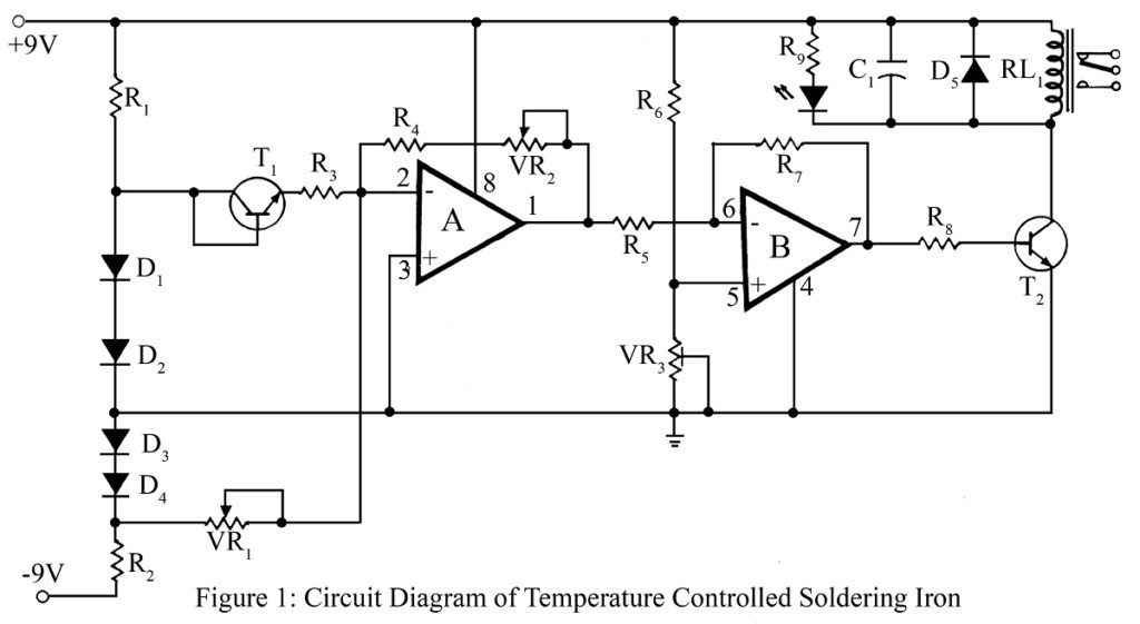
Temperature-controlled soldering stations are now readily available in the market. Such instruments use thermocouples or thermistors as temperature sensors. But even if it’s available in markets it’s fun and experience to build this device yourself. An electronics hobbyist would surely like to build this unit to enhance the working life of his soldering iron bit and to save power. With a basic knowledge of comparators, this circuit “Temperature controlled soldering iron station” is very easy to understand.
Transistor T1 BC107 is used here as a temperature sensor. The fact that the emitter to base turn-on voltage of a silicon transistor is linear with temperature, is utilized to sense temperature. If the operating current of the sensing transistor is made proportional to absolute temperature, the small non-linearity which is prevailing can be eliminated.
Diode D1 and D2 provide a voltage source of 1.2 V, which is applied through resistor R3 to set the operating current of transistor T1. Here variable resistor VR1 biased the input of amplifier for zero output at zero degree centigrade, while VR2 can be calibrated for 100mV/0C at pin 1 of IC1.
IC1(B) acts as a simple comparator. Resistor R7 provides some hysteresis. Preset VR3 can be varied to control the temperature of soldering from about 2500C to 4500C.
Transistor T2 drives the relay. If the temperature of soldering increases above the set value, output at pin 7 of IC1 goes high and T2 gets base drive. The relay operates and the soldering iron is cut off from the supply. When the temperature of iron comes within the range of the set limit, the output at pin 7 goes low, thus tripping the relay. And then the soldering iron is again connected to the supply. Capacitor C1 eliminates the relay flutter at the time of changing the logic levels at pin 7 of IC1.
The sensor may be mounted a half-centimeter away from the soldering iron bit with a single-core copper wire. Use mounting sockets for IC.
For calibration of the system adjust VR1 and VR2 at positions slightly greater than their mid-positions. In this case, the voltage at pin 1 will be around 4.8V.
Connections of VR3 are to be made such that rotating VR3 from its minimum position in a clockwise direction will decrease the voltage at pin 5 of IC1. When VR3 is in minimum position the voltage at pin 5 of IC1 is around 4.2 volts. When VR3 is at maximum the voltage at pin 5 will be zero volts.
PARTS LIST OF TEMPERATURE CONTROLLED SOLDERING IRON STATION
|
Resistors (all ¼-watt, ± 5% Carbon) |
|
R1, R2 = 10 KΩ R3 = 3.9 KΩ R4, R6 = 100 KΩ R5 = 47 KΩ R7 = 1 MΩ R8 = 1.5 KΩ R9 = 330 Ω VR1 = 4.7 KΩ VR2 = 100 KΩ VR3 = 470 KΩ |
|
Capacitor |
|
C1 = 470 µF, 16V (Electrolytic Capacitor) |
|
Semiconductors |
|
IC1 (A, B) = LM358 (low power dual operational amplifier) T1 = BC107 (Low Power Bipolar Transistors) T2 = BC517 (NPN Bipolar Darlington Transistor) D1 – D4 = 1N4148 (silicon switching signal diode) D5 = 1N4001 (Rectifier Diode) LED1 |
|
Miscellaneous |
|
RL1 = 9V, 100 Ω Relay |
