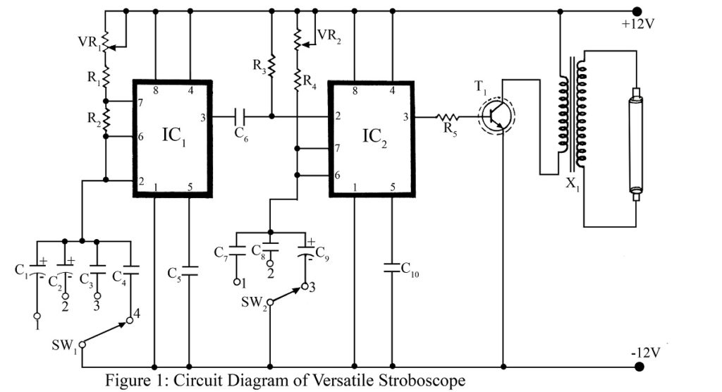
Introduction to the Strobe Light Circuit
A stroboscope is an electronic device designed to observe rapidly moving objects that exhibit periodic motion as though they are stationary. This effect is achieved by flashing a strobe light at a frequency that synchronizes with the object’s motion, such as the rotation of a wheel, making it appear as if it is not moving. The strobe light circuit using a 555 timer IC utilizes a neon lamp, but for better visibility and illumination, a 9-inch tube light is recommended.
PARTS LIST OF STROBE LIGHT CIRCUIT USING 555 IC
Resistors (all ½ -watt, ± 5% Carbon)
R1, R3 = 10 KΩ
R2 = 4.7 KΩ
R4 = 6.8 KΩ
R5 = 270 Ω
VR1, VR2 = 100KΩ (POT.)
Capacitors:
C1 = 10 µF/25V (Electrolytic Capacitor)
C2, C9 = 1 µF/25V (Electrolytic Capacitor)
C3, C8 = 0.1 µF (Ceramic Disc)
C4 – C7, C10 = 0.01 µF (Ceramic Disc)
Semiconductors:
IC1, IC2 = NE555 (Timer IC)
T1 = 2N3055 (silicon power transistor)
Miscellaneous:
X1 = 220V AC primary to 0-6V, 500mA secondary transformer used in reversed mode.
SW1 = Single pole 4-way switch
SW2 = Single pole 3-way switch
9-inch fluorescent tube.
Circuit Description and Operation
The strobe light circuit, shown in Figure 1, uses two NE555 timer ICs configured as an astable and monostable multivibrator:
1. Astable Multivibrator (IC1)
- IC1 is set up in an astable multivibrator mode, acting as a pulse generator. Its frequency is adjustable using a variable resistor VR1.
- A rotary switch SW1 allows the frequency range to be selected, making it possible to vary the pulses from 1.2 Hz to 12 kHz.
- The output pulse from pin 3 of IC1 is then connected to pin 2 (trigger pin) of IC2 via a coupling capacitor C6.
2. Monostable Multivibrator (IC2)
- IC2 is configured as a monostable multivibrator, generating a single pulse with an adjustable width, controlled by variable resistor VR2.
- The pulse width ranges from 100 microseconds to 100 milliseconds and can be set using rotary switch SW2.
- The output from IC2 (pin 3) is fed to the base of the power transistor 2N3055 (T1) through a current-limiting resistor R5.
3. Power Stage and Transformer (X1)
- The transistor’s output is connected to the secondary winding of transformer X1 (6V-0V secondary) in reverse (used as a step-up transformer).
- The 6V terminal of the transformer is connected to a 12V DC supply, while the 0V terminal is linked to the transistor’s output.
- When the transistor oscillates, it generates a stepped-up current in the transformer, sufficient to light up the tube light.
4. Synchronizing the Light with Motion
- To sync the strobe light with something moving, like the blades of a fan, start by pointing the light at it. Then, adjust the circuit’s frequency and pulse width. As you make these adjustments, the flashes of the strobe light will start to match up with how fast the object is moving. When everything lines up just right, the object will look like it’s standing still, even though it’s moving. Once in sync, the light creates an effect that makes the moving object appear stationary, even though it’s still in motion.
Note:
- For larger tube lights, a driver stage and an inverter transformer may be required to provide adequate power.
This strobe light circuit, built with 555 timer ICs, offers a hands-on way to learn about multivibrators and pulse generation. This strobe light circuit is quite handy and and is used for various practical tasks. Whether you need to measure the speed of moving objects, sync with something rotating, or check for issues in machinery, this circuit makes those jobs easier.
Using the flexibility of the 555 timer IC along with a straightforward power stage, this circuit makes for a great project. This circuit is a great fit for electronics hobbyists, students, or professionals who are interested in experimenting with strobe lighting or gaining a better understanding of timing circuits.
You may also like
- DIY Strobe Light Circuit
- Strobe Light using Arduino
- High power Strobe light using Arduino
- High brightness led strobe light using timer IC 555
