Many attempts have been made in the past to determine the relationship between the dynamic resistance of a pile during driving and static load carrying capacity of the pile. These relationships are called pile driving formula and have been established theoretically and empirically. Of many pile – driving formula, which have been, proposed Engineering News Formula, Hiley Formula and Janbu Formula are widely used. Among these the Hiley Formula and Janbu Formula are convenient to use and give reasonable predictions of ultimate bearing capacity of driven piles in granular soils.
Engineering News Formula
As per the Engineering News formula the allowable load of driven pile is given by:
Where, Qa = Allowable load in kg
W = Weight of hammer
h = Height of fall in cms
s = Final settlement per blow known as set
c = Empirical constant (c = 2.5 cm for drop hammer and 0.25 cm for single acting and double acting hammer)
F = Factor of safety (Usually taken as 6)
Janbu Formula
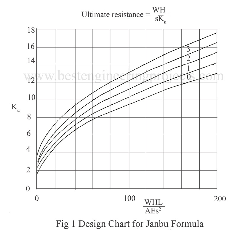
The relation suggested by Janbu for ultimate capacity of the pile is:
———- (1)
Where, ———- (2)
———- (3)
and ———- (4)
Where, = Empirical constants
H = Height of fall
W = Weight of hammer
Wp = Weight of pile
L = Length of pile
A = Cross-sectional area
E = Modulus of elasticity of pile material
s = Final set
= Efficiency factor
The design chart is given in Fig.1. The efficiency factor is dependent on the pile driving equipment, the driving procedure adopted, the type of pile and the ground conditions. Values of
can be chosen as follows.
= 0.7 for good driving conditions
= 0.55 for average driving conditions
= 0.4 for difficult or bad driving conditions
Hiley Formula
The relation suggested by Hiley for ultimate bearing capacity of the pile is:
———- (5)
Where, K = Hammer coefficient
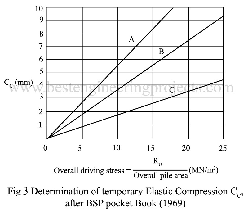
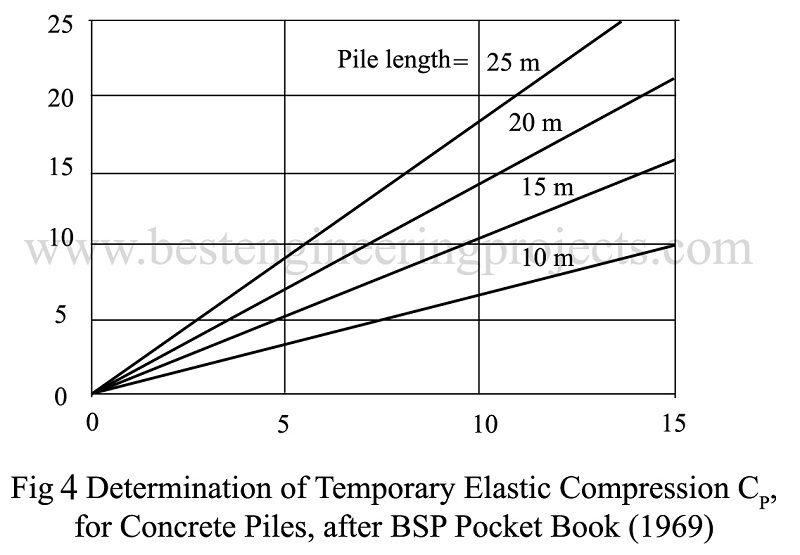
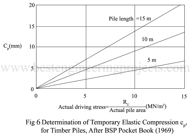
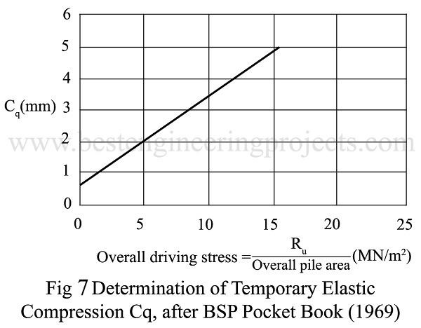
c = Sum of elastic compression ( c = cp + cc + cq)
cp = Compression of pile
cc = Compression of pile head
cq = Compression of ground
W = Weight of hammer
H = Height of fall of hammer
s = Final Set
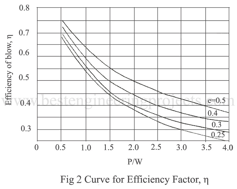
= Efficiency of blow
It should be noted that depends on the coefficient of restitution, which is given in Table 2,
being obtained from Fig.2. Hammer coefficient is given in Table 1
Table 1 Values of Hammer Coefficient K
|
Hammer |
K |
|
Drop Hammer, Winch operated |
0.8 |
|
Drop Hammer, Trigger release |
1.0 |
|
Single Acting Hammer |
1.9 |
|
BSP Double Acting Hammer |
1.0 |
|
McKiernan-Terry Diesel Hammers |
1.0 |
Values of cp, cc, cq and can be obtained from figs.2 to 7.
A = concrete pile, 75 mm packing under helmet
B = concrete or steel pile, helmet with dolly or head of timber pile
C = 25 mm pad only on head of RC pile
Comparison of Formula
A detailed investigation into the validity of pile driving formula suggests that there is little to choose between the Hiley and Janbu formula. In order to obtain minimum factor of safety of 1.75 for any one pile, it has been shown that it is necessary to use F = 2.7 with the Hiley formula and VF = 3 with the Janbu formula. Janbu formula gives e slightly better correlation between tested and calculated bearing capacity.
Overdriving of Piles
It is sometimes necessary to drive piles through dense sands and gravels, for example, either to penetrate an underlying clay layer, or because of the possibility of scour in riverbeds. Damage to the pile due to overdriving must be avoided, both when penetrating an overlying hard layer and when driving into the bearing stratum to develop the full healing capacity. In this condition it should be remembered that a penetration up to five pile diameters into dense granular material may be necessary to develop fully end bearing capacity.
Table 7.3 Values of the Coefficient of Restitution, e, after BSP Pocket Book (1969)
|
Types of pile |
Head Condition |
Single acting or drop-hammer or diesel-hammer |
Double acting hammer |
|
Reinforced Concrete |
Helmet with composite plastic or Greenheart dolly and packing on top of pile |
0.4 |
0.5 |
|
Helmet with timber dolly (not Greenheart) and packing on top of pile |
0.25 |
0.4 |
|
|
Hammer directly on pile with pad only |
– |
0.5 |
|
|
Steel |
Driving cap with composite plastic or Greenheart dolly |
0.5 |
0.5 |
|
Driving cap with timber (not Greenheart dolly) |
0.3 |
0.3 |
|
|
Timber |
Hammer directly on pile |
– |
0.5 |
|
Hammer directly on pile |
0.25 |
0.4 |
The Hiley formula can be used to determine the failure load, Qu, and then the peak driving resistance, Pd is given by:
Janbu suggests that the driving energy (WH)c, needed to avoid damage is limited by:
———- (6)
Where, L = length of pile
s = set
A = cross-sectional area of the pile
= half of compressive strength
Various Other article related to piled foundation posted in bestengineeringprojects.com, you may like
- Behavior of Single Pile and Pile Group Under Loads
- Load Carrying Capacity Pile
- Bored and cast-In-Place Piles
- Construction of Pile Foundation
- Pile Load Test | Purpose of Pile Load Test

Howw we can get the pile capacity by given piling summary record and set criteria report. For example, pile penetration =24.9m, final 10 blow set reading = 38mm, design ultimate capacity 120Kn,factor of safety 2.0,hammer efficiency 0.8,weight of hammer 5 tonne, weight of pile 3.54 tonne( dia 300mm spun pile),coefficient of restitution 0.55,assume compression 0.016m and drop of hammer 0.55m.
Thanks for help..hiley formula is using.