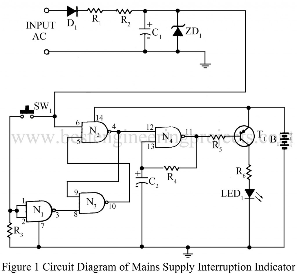
The Mains Supply interruption indicator circuit can be used in applications where it is necessary to know whether the mains supply has been continuous or not. The circuit mains supply interruption indicator will be useful for monitoring mains supplies to recording equipment, especially in the recording of computer software tapes, where the slightest interruption in the mains supply will cause an error in the data being recorded. It can also be used with digital clocks working on mains. An interruption in the mains supply will cause an LED to flash as a warning that the mains supply was interrupted.
Description of Mains Supply Interruption Indicator Circuit
The circuit main supply interruption indicator is very simple and straightforward as it is based on just one CMOS IC. IC1 contains four NAND Schmitt trigger gates. This IC has been chosen to keep the current consumption and component count to a minimum.
N1 has been wired as an inverter with its input connected to the reset switch. The reset switch will operate only when the main supply is present. N2 and N3 form a simple S-R latch.
One of the inputs of N2 has been connected to the low voltage DC supply derived from the mains. The output of the latch is connected to the oscillator formed by N4. The output of the oscillator has been connected to an LED. The LED and IC have powered off a 4.5V supply derived from three 1.5V cells.
The oscillator is enabled whenever the input of N2 is low. i.e the mains supply is absent, causing the LED to flash. The LED continues to flash even after the mains supply has resumed until the reset button is pressed. The circuit may be assembled on a general-purpose PCB. Care should be taken while testing the circuit at the main potential. If an audible alarm is desired, the LED can be replaced by a buzzer after making suitable changes in the value of R6.
PARTS LIST OF MAINS SUPPLY INTERRUPTION INDICATOR CIRCUIT
|
Resistor (all ¼-watt, ± 5% Carbon) |
|
R1, R2 = 100 KΩ, 1/2W R3, R5 = 10 KΩ R4 = 100 kΩ R6 = 560 Ω |
|
Capacitors |
|
C1 = 1 µF, 16V (Electrolytic Capacitor) C2 = 4.7 µF, 6.3V (Electrolytic Capacitor) |
|
Semiconductors |
|
IC1 = 4093 (Quad Schmitt-trigger IC) T1 = BC157 (Low Power and General Purpose PNP Transistor) D1 = 1N5402 (General Purpose Rectifier Diode) ZD1 = 6.8V Zener diode |
|
Miscellaneous |
|
B1 = 4.5V battery SW1 = Push-to-on Switch LED1 |
