In this article, we will discuss Magnetron and basic Magnetron Operations. The magnetron is an oscillator unlike any other that. A magnetron is a self-contained unit. That is, it produces a microwave frequency output within its enclosure without the use of external components such as crystals, inductors, capacitors, etc. Check out the article on the Application of Microwave.
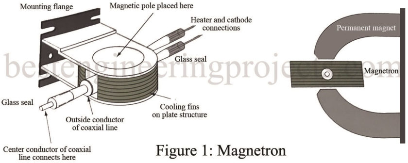
Basically, the magnetron is a diode and has no grid. A magnetic field in the space between the plate (anode) and the cathode serves as a grid. The plate of a magnetron does not have the same physical appearance as the plate of an ordinary electron tube. Since conventional LC networks become impractical at microwave frequencies, the plate is fabricated into a cylindrical copper block containing resonant cavities that serve as tuned circuits. The magnetron base differs greatly from the conventional base. It has short, large-diameter leads that are carefully sealed into the tube and shielded, as shown in Figure 1.
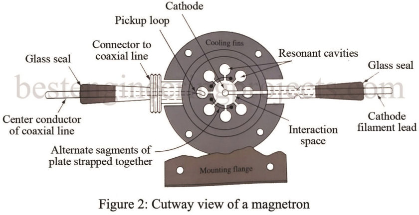
The cathode and filament are at the center of the tube. The cathode is supported by the filament leads, which are large and rigid enough to keep the cathode and filament structure fixed in position. The output lead is usually a probe or loop extending into one of the tuned cavities and coupled into a waveguide or coaxial line. The phase structure, as shown in Figure 2, is a solid block of copper. The cylindrical holes around its circumference are resonant cavities. A narrow slot runs from each cavity into the central portion of the tube and divides the inner structure into as many segments as there are cavities. Alternate segments are strapped together to put the cavities in parallel with regard to the output. These cavities control the output frequency. The straps are circular metal bands that are placed across the top of the block at the entrance slots to the cavities. Since the cathode must operate at high power, it must be fairly large and must be able to withstand high operating temperatures.
It must also have good emission characteristics, particularly under back bombardment, because much of the output power is derived from the large number of electrons emitted when high-velocity electrons return to strike the cathode. The cathode is indirectly heated and is constructed of a high-emission material. The open space between the plate and the cathode is called the interaction space because it is in this space that the electric and magnetic fields interact to exert force on the electrons.
The magnetic field is usually provided by a strong permanent magnet mounted around the magnetron so that the magnetic field is parallel with the axis of the cathode. The cathode is mounted in the center of the interaction space.
Basic Magnetron Operation
The theory of magnetron operation is based on the motion of electrons under the influence of combined electric and magnetic fields. The direction of an electric field is from the positive electrode to the negative electrode. The law governing the motion of an electron in electric, or E, field states that the force exerted by an electric field on an electron is proportional to the strength of the field. Electrons tend to move from a point of negative potential toward a positive potential. In other words, electrons tend to move against the E field. When an electron is being accelerated by an E field, energy is taken from the field by the electron. The law of motion of an electron in a magnetic, or H, field states that the force exerted on an electron in a magnetic field is at right angles to both the field and the path of the electron.
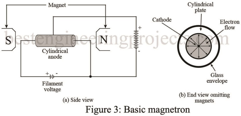
A schematic diagram of a basic magnetron operation is shown in Figure 3(a). The tube consists of a cylindrical anode with a cathode placed coaxially with it. The tuned circuit (not shown) in which oscillations take place is a cavity physically located in the anode.
When no magnetic field exists, heating the cathode results in a uniform and direct movement in the field from the cathode to the plate, as illustrated in Figure 3(b).
Effect of Magnetic Field in Magnetron Operation
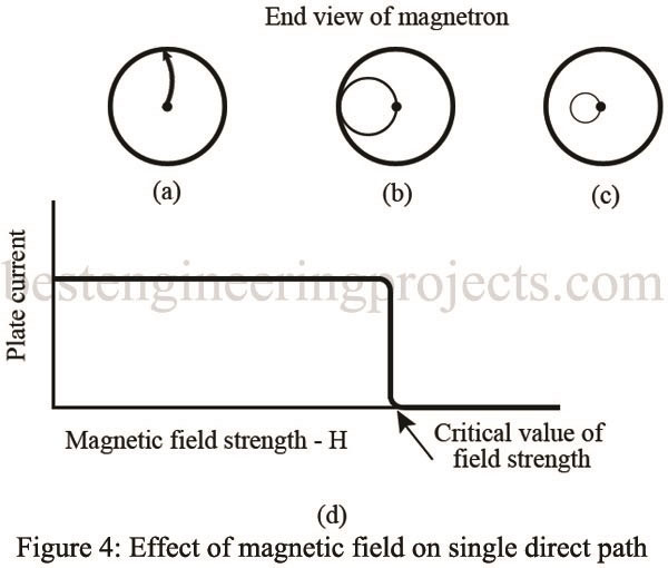
However, as the magnetic field surrounding the tube is increased, a single electron is affected, as shown in Figure 4. In Figure 4(a), the magnetic field has been increased to a point where the electron proceeds to the plate in a curve rather than a direct path.
In Figure 4(b), the magnetic field has reached a value great enough to cause the electron to just miss the plate and return to the filament in a circular orbit. This value is the critical value of field strength. In Figure 4(c), the value of the field strength has been increased to a point beyond the critical value, and the electron is made to travel to the cathode in a circular path of smaller diameter.
Figure 4(d) shows how the magnetron plate current varies under the influence of the varying magnetic field. In Figure 4(a), the electron flow reaches the plate so that there is a large amount of plate current flowing. However, when the critical field value is reached, as shown in Figure 4(b), the electrons are deflected away from the plate, and the plate current drops abruptly to a very small value. When the field strength is made still larger [Figure 4(c)] the plate current drops to zero.
When the magnetron is adjusted to the plate current cutoff or critical value and the electrons just fail to reach the plate in their circular motion, the magnetron can produce oscillations at microwave frequency by virtue of the currents induced electrostatically by the moving electrons. This frequency is determined by the size of the cavities. Electrons are accelerated toward the anode by the electric field and bent by the magnetic field so that they travel parallel to the anode. If they pass the anode gap at a time when they are traveling in the same direction as the electric field in the gap, they slow down and thus give up energy (kinetic) to the electric field in the cavity. This reinforces the oscillations and is the basis of operation.
A transfer of microwave energy to a load is made possible by connecting an external circuit between the cathode and plate of the magnetron. Magnetrons are widely used as sources of microwave power up to 100 GHz. They can provide up to 25 kW of continuous power at efficiencies up to 80%. Pulsed magnetrons are used in radar applications up to 10,000 KW with low duty cycles. They are also widely used for microwave ovens. They operate at 2.45 GHz with continuous outputs of 400 to 1000 W. Their electromagnetic energy is radiated through the food, which is heated (cooked) from the inside out. These tubes have been highly refined due to this volume application and offer reliability such that they can be expected to outlive the average expected 10- to 15year life for a home appliance. Since the magnetron is functionally a diode, the only other power supply component required is a transformer for the 2 to 4 kV and the filament voltage.


