Op-amp 741 IC is one of the most popular and versatile operation amplifiers and can be used in a lot of applications including, comparators, wave generator amplifiers, etc. Today, we came up with another application of 741 IC i.e. Square Wave Generator using 741 IC.
Objectives of Square Wave Generator using 741 IC:
- To design a square wave generator
- To describe the working of the square wave generator.
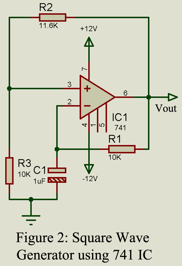
Circuit diagram of the square wave generator
The circuit of the square wave generator is shown in the figure below. One capacitor is connected to inverting terminal of an op-amp with one pin connected to the ground, and a resistor for charging and discharging the capacitor is also connected to inverting terminal to output as shown in the circuit diagram. One voltage divider is designed using resistor R2 and R3, where two ends of this voltage divider are connected to the output and the ground, and the middle joint is connected to the non-inverting pin.
As usual, we will provide a positive and negative power supply to pin 7 and pin 4 of IC1 (LM741), where output is obtained from pin 6.
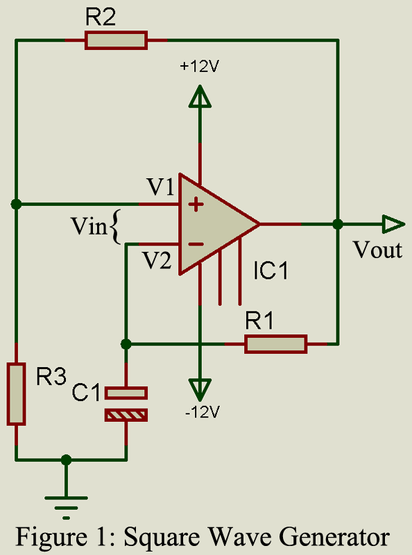
If we force that output to switch between the positive saturation voltage as well as negative saturation voltage then we can achieve the square wave as an output from the circuit.
Working of Square Wave Generator using 741 IC
Let us consider the voltage at inverting terminal to be V2 which is nothing but the voltage across the capacitor C. Similarly, let us also consider the voltage at the non-inverting terminal to be V1. The voltage difference between the non-inverting and inverting terminals is referred to as differential input voltage and is given by Vin.
V2 = Vc (Voltage across capacitor C1)
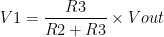
V1 = Voltage between resistor R2 and R3 at offset.
(Offest voltage: Voltage at the output when no input is given)
So, by using the voltage divider formula we can calculate the voltage at the non-inverting terminal
Case 1: At the initial state when the capacitor is fully discharged, the voltage at inverting pin will be zero i.e. V2 = 0V
Therefore, input differential voltage (Vin) = V1-V2 = V1-0 = V1
When Vin is positive the output is also positive, at this instance the capacitor C1 starts to charge through resistor R1 towards positive saturation voltage until V1 = V2.
Case 2: When the voltage at capacitor C1 increases slightly more than V1 differential voltage also because negative Vin = V1-V2 (V2>V1). Then the output will be switched from positive saturation voltage to negative saturation voltage. At this instance, the capacitor starts to discharge through resistor R1 because V2 becomes greater than Vout. Again, after reaching V2 slightly less than V1 the output will switch to positive saturation voltage. This process repeats again and again as a result square wave is generated.
Now, we get the square wave which will switch between positive saturation voltage and negative saturation voltage.
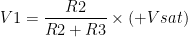
The equation of V1 is changed according to the output.
When the output is positive
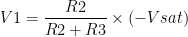
When output is negative,
Therefore, Magnitude of 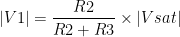
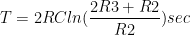
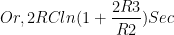
The time period ‘T’ of the square wave can be calculated as,
The frequency of square wave can be calculated as  and is independent of output voltage Vout.
If we put R2 = 1.16R1

T = 2Rc X 1
T = 2RC
Therefore, 
IF we put C as constant then the frequency is inversely proportional to resistance R.
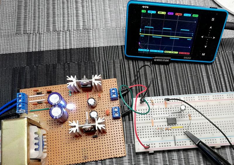
Figure: Author Prototype of Square Wave Generator
Design a circuit using 741 op-amps which generate the square wave of 50 Hz.
Solution:
Let’s C = 1 uF
If we consider the condition of T = 2RC, then R2 = 1.16R3.
Let, R3 = 10 k-ohm
Then, R2 = 1.16 x 10k-ohm
R2 = 11.6k-ohm
We know that 
Therefore, 


From above calculation we find the value of every components
R1, R3 = 10k-ohm
R2 = 11.6k-ohm
C1 = 1 uF