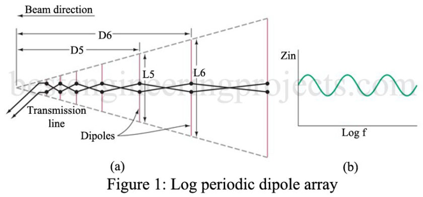
The log-periodic antenna is a special case of a driven array. It was first developed in 1957 and has proven so desirable that its many variations now make up an entire class of antennas. It provides reasonably good gain over an extremely wide range of frequencies. It is, therefore, useful for multiband transceiver operation and as a TV receiving unit to cover the entire VHF and UHF bands. It can be termed a wide-bandwidth or broad-band antenna. Bandwidth is not to be confused with beamwidth in this situation. Check out the article on Yagi Uda Antenna, Marconi Antenna.
Antenna bandwidth is defined concerning its design frequency, often termed its center frequency. If a 100-MHz (center frequency) log-periodic antenna is transmitted or received power is 3 dB down at 50 MHz and 200 MHz, its bandwidth is 200 MHz – 50 MHz or 150 MHz. This measurement is made in the direction of the highest antenna directivity.
The most elementary form of log-periodic antenna is shown in Figure 1(a). It is termed a log-periodic dipole array and derives its name from the fact that its important characteristics are periodic concerning the logarithm of the frequency. This is true of its impedance. Its SWR with a given feed line, and the strength of its radiation pattern. For instance, its input impedance is shown to be nearly constant (but periodic) as a function of the log of frequency in Fig. 14-21(b).
The log-periodic array in Fig. 14-21(a) is seen to consist of a number of dipoles of different lengths and spacings. The dipole lengths and spacings are related by
where is called the design ratio with a typical value of 0.7. The range of frequencies it is usul over is determined by the frequencies at which the longest and shortest dipoles are a half wavelength.
