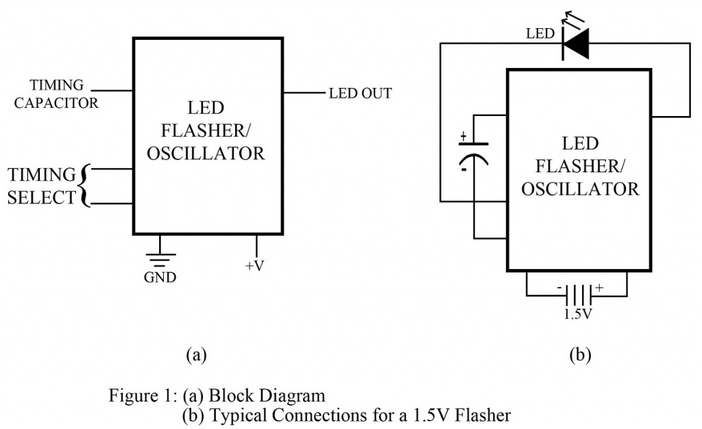
LEDs are probably the only components to offer a wide range of applications. It can be used either to describe the working of the circuit or with LED itself, a complete circuit can be developed. The LED flasher circuit makes use of this amazing component to turn it flash on and off. The LED flasher circuit employs a voltage source, capacitor, and LED.
This project requires voltage supplies varying from 1.15 volts to 6 volts typically because of which the circuit can be operated with a single battery cell making it more economical. In addition to this, the power drain has been optimized to prolong the battery life. The external electrolytic capacitor not only controls the flash rate but also is used to supply a voltage boost to the LED for maximum brightness. The frequency provided at the output can be adjusted slow enough (1 Hz) for LED flashing applications or can also be made faster (1 kHz). At a faster rate, audio tones can be produced which can be used to directly drive an 8-ohm speaker.
Basic key parameters of LED flasher circuit are explained in points below:
- Flash frequency: – It is the frequency at which the LED will flash on and off. The desired frequency is chosen by the selection of an electrolytic capacitor. Since this type of capacitor has a tolerance that can vary from – 20% to +100%, the accuracy of the flash rate is often determined by trial and error.
- Estimated battery life: – These are guidelines provided by the manufacturer to give an indication of expected battery life. 15 months continuous operation with a C cell alkaline battery is a typical example.
Applications of LED Flasher Circuit
Generally, this chip is used in toys for flashing lights or siren effects. The chip is also useful for warning devices or as a source for square wave generation. With slight modifications in the circuit, the chip can be used to produce the output we desire.
Check out the various project based on LED posted in bestengineeringprojects.com
Check out other top popular Articles :
Clock Signal Generator Circuit
