Electricity is a mystery. We use it, we pay for it, but do we really understand how much each device is consuming? Ever felt like your electricity bill was higher than it should be, but you couldn’t pinpoint the culprit? Well, my friend, today we’re gonna unmask those energy-hogging appliances by building an AC Power Monitor using Arduino and ACS712!
This little DIY project is like giving your home X-ray vision for power usage. You’ll be able to measure voltage, current, and power consumption in real time. And, as a bonus, it’s fun to build. Seriously, watching numbers change on a screen never felt more satisfying.
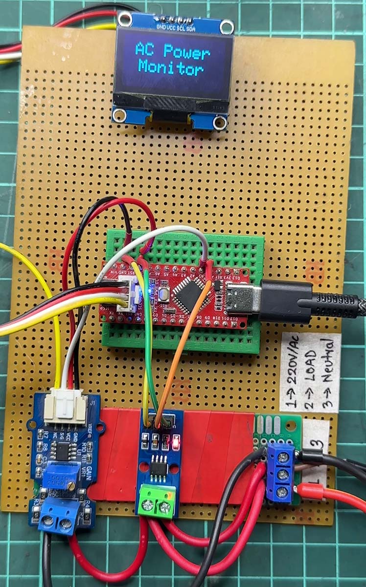 Figure: Prototype of AC Power Monitor using Arduino
What’s the Plan?
We’re making a simple AC power monitoring system using an Arduino Nano, an ACS712 5A current sensor, a voltage sensor module, and an OLED display. Once it’s up and running, you’ll have a real-time energy meter, just like those expensive smart meters—except you built it yourself!
By the end of this project, you’ll be able to:
- Measure AC Voltage (like checking how “full” a river is before stepping in).
- Measure AC Current (think of it as knowing how fast the river is flowing).
- Calculate Power (Watts) (because volts x amps = power).
- See it all on an OLED display in real-time.
Quick Note: AC voltage measurement is tricky (you can’t just stick your Arduino into a wall socket—unless you wanna BBQ your board). We’re doing it safely, but if you want a deeper dive into the process, check this:
How to Measure AC Voltage Using Arduino Without Transformer
Stuff You’ll Need
- Arduino Nano (or Uno, but Nano fits nicely on a small PCB).
- ACS712 5A Current Sensor (because guessing current is not an option).
- Voltage Sensor Module (so we don’t fry the Arduino).
- OLED Display (128×64, I2C) (real-time data, baby!).
- A Light Bulb or Fan (AC Load) (something to test with).
- Breadboard & Jumper Wires (because floating components are not a vibe).
Wiring Everything Up
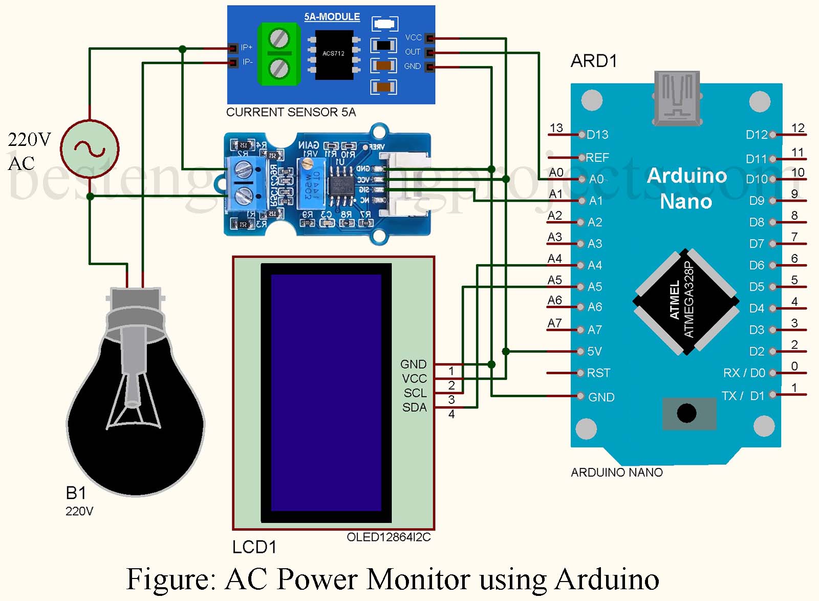
Here’s how the magic connects:
- ACS712 Current Sensor:
- IP+ / IP- → Connect in series with the live wire.
- VCC → Arduino 5V, GND → Arduino GND.
- OUT → Arduino A0 (Reads current).
- Voltage Sensor Module:
- VCC → Arduino 5V, GND → Arduino GND.
- OUT → Arduino A1 (Reads voltage).
- OLED Display (I2C Communication):
- SDA → A4 (Arduino), SCL → A5 (Arduino).
- VCC → 5V, GND → GND.
The Code That Brings It All to Life
This is where the numbers start dancing. Upload the code below, and your power monitor will be ALIVE.
|
1 2 3 4 5 6 7 8 9 10 11 12 13 14 15 16 17 18 19 20 21 22 23 24 25 26 27 28 29 30 31 32 33 34 35 36 37 38 39 40 41 42 43 44 45 46 47 48 49 50 51 52 53 54 55 56 57 58 59 60 61 62 63 64 65 66 67 68 69 70 71 72 73 74 75 76 77 78 79 80 81 82 83 84 85 86 87 88 |
#include "MCMVoltSense.h" // Include MCM Volt Sense Library #include <Wire.h> #include <Adafruit_GFX.h> #include <Adafruit_SH110X.h> #define i2c_Address 0x3C // I2C Address for SH1106 #define SCREEN_WIDTH 128 // OLED display width #define SCREEN_HEIGHT 64 // OLED display height Adafruit_SH1106G display = Adafruit_SH1106G(SCREEN_WIDTH, SCREEN_HEIGHT, &Wire); MCMmeter meter; // Create an instance #define CURRENT_SENSOR A0 // ACS712 5A sensor connected to A0 const float ACS712_SENSITIVITY = 0.185; // Sensitivity for 5A version (185mV/A) const float REFERENCE_VOLTAGE = 5.0; // Reference voltage (Arduino: 5V) const int ADC_RESOLUTION = 1024; // 10-bit ADC resolution const int NUM_SAMPLES = 200; // Number of samples for better accuracy const float NOISE_THRESHOLD = 0.05; // Minimum detectable current (A) // **Offset Calibration (Measure ACS712 output at zero load and update)** float ACS712_OFFSET = 2.52; // Default is 2.5V, but may need fine-tuning void setup() { Serial.begin(115200); // Initialize OLED display if (!display.begin(i2c_Address, true)) { Serial.println("SH1106 allocation failed"); for (;;); } display.clearDisplay(); display.setTextSize(2); display.setTextColor(SH110X_WHITE); display.setCursor(15, 10); display.print("AC Power"); display.setCursor(20, 30); display.print("Monitor"); display.display(); delay(3000); display.clearDisplay(); meter.VoltageStp(A1, 122.65, 1.7); // Voltage: input pin, calibration, phase_shift } float measureACCurrent() { float sumSq = 0; float offsetVoltage = ACS712_OFFSET; for (int i = 0; i < NUM_SAMPLES; i++) { int rawValue = analogRead(CURRENT_SENSOR); float voltage = (rawValue / (float)ADC_RESOLUTION) * REFERENCE_VOLTAGE; float current = (voltage - offsetVoltage) / ACS712_SENSITIVITY; sumSq += current * current; // Square the current readings delayMicroseconds(500); // Small delay to capture AC waveform points } float Irms = sqrt(sumSq / NUM_SAMPLES); if (Irms < NOISE_THRESHOLD) { Irms = 0.0; } return Irms; } void loop() { unsigned long currentMillis = millis(); meter.analogVoltage(40, 2000); float Vrms = meter.Vrms; float Irms = measureACCurrent(); float Watt = Vrms * Irms; Serial.print("Voltage: "); Serial.print(Vrms, 2); Serial.print(" V, Current: "); Serial.print(Irms, 3); Serial.print(" A, Power: "); Serial.print(Watt, 2); Serial.print(" W, Energy: "); display.clearDisplay(); display.setTextSize(2); display.setCursor(20, 10); display.print(Vrms, 1); display.print("V"); display.setCursor(20, 30); display.print(Irms, 2); display.print("A"); display.setCursor(20, 50); display.print(Watt, 1); display.print("W"); display.display(); delay(2000); } |
Tuning the Offset for Accuracy
Here’s a common mistake people make:
They upload the code, look at the Serial Monitor, and go, “Why is it showing 0.10A when no load is connected?”
That’s because the ACS712 has an idle offset (it doesn’t start at exactly 2.5V).
How to Fix It?
- Remove all load (disconnect any appliance).
- Check Serial Monitor.
- If the current is not precisely 0.00A, adjust:
|
1 |
float ACS712_OFFSET = 2.52; // Tweak this value until the reading is 0.00A at no load. |
Bingo! Now, your readings are accurate.
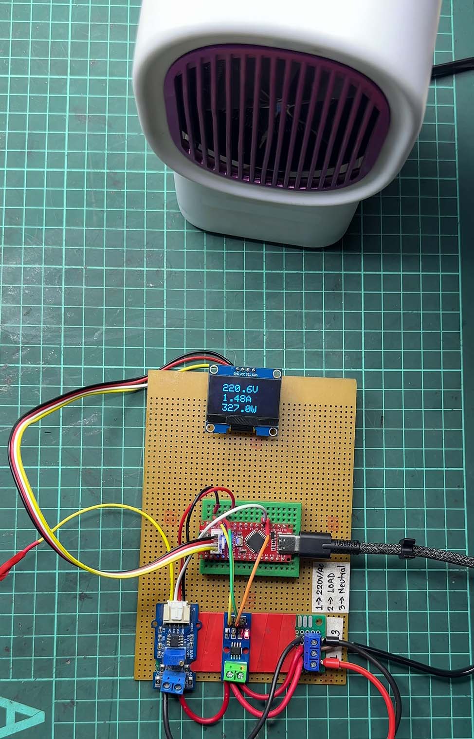 Figure: AC Power Monitoring with Load
Final Thoughts
You just built a working Arduino AC Power Monitor! How cool is that?
Now, you can track your power consumption, optimize energy use, and impress your friends.
So what’s next? Maybe…
- Send this data wirelessly using ESP32.
- Log it to an SD card?
- Make a full home energy monitoring system.
Whatever it is, keep building, keep learning, and keep having fun!
Comment below if you built this, I’d love to hear your experience!