The project GPS and GSM-based Vehicle Tracking System uses Global Positioning System (GPS) and global system for mobile communication (GSM), which makes this project more economic than implementing a communication system through GPS satellites in a two-way GPS communication system.
Introduction to GPS and GSM based Vehicle Tracking System
Tracking has now been a recent trend followed everywhere. This process helps us to collect details and at the same time prevent robbery of devices being tracked. The project ‘GPS and GSM based Vehicle Tracking System’ which employs a microcontroller as its chief component is mostly implemented to keep track of vehicles in recent times. The ‘GPS and GSM based Vehicle Tracking System’ project utilizes a GSM modem as a replacement for one of the GPS devices to ensure a two-way communication process. The GSM modem and SIM card combination employ the same technique as a normal cell phone to implement the tracking process.
The overall system of ‘GPS and GSM based Vehicle Tracking System’ is so easy and simple that it can be executed anywhere. This device can either be fixed or mounted in any corner of the vehicle or an expensive piece of equipment that needs protection. Yes, we can also track equipment with this device when planted properly. Once the proper installation process is followed, we now have total access to the pathway of the vehicle or any object under consideration. Through the help of our mobile phones, we get complete information about the whereabouts of that applicant.
Other project-based on GPS posted in bestengineeringprojects.com
- GPS Module Interface with ATmega16
- DIY Distance Measurement using GPS and ATmega328P
- GPS Navigator Circuit using ATmega 16
- Accident Detection and Alert System using Arduino
The key component in the project ‘GPS and GSM based Vehicle Tracking System’ is a small chip i.e. SIM attached to the GSM modem which relays the current location of that object in the text format i.e. SMS back in the phone once the mobile number of that SIM is dialed. There is no particular time limit set for this project, user can request for the location of the object at any time and any location where the mobile network is reachable. Be it either a fleet of vehicles or a number of expensive equipment’s, this project is applicable everywhere to locate them anywhere and at any instant despite the long distance. The fact that it allows people to achieve information they need from a distant place without having them be physically present there makes it more flexible.
Circuit Description of GPS and GSM Based Vehicle Tracking System: –
The circuit diagram of the project “GPS and GSM based vehicle tracking system” is depicted in fig.1. As we can see clearly, the chief components employed in this project are: microcontroller, GPS module, GSM modem, and 9V DC supply as a source of power for the project. The working of the project ‘GPS and GSM based vehicle tracking system’ can be summarized in points below:
- The location detail of the vehicle/object is collected by the GPS module from the satellite, this information is in the form of latitudes and longitudes scale.
- Thus collected information is then fed to the microcontroller. Necessary processing is done and then the information is passed onto the GSM modem.
- The GSM modem collects the information for the microcontroller and then transfers it to the mobile phone through the SMS which is in text format.
Components Description of GPS and GSM based Vehicle Tracking System: –
ATmega16 microcontroller
This microcontroller (IC2) is the major component that performs as the brain of the project. It acts as an interfacing medium in between multiple hardware peripherals used in this project. The IC is an 8-bit CMOS based on the AVR enhanced RISC architecture which consumes less power to operate.
We use a serial interfacing technique to connect this IC2 with a GPS module and GSM modem. Out of the multiple data generated by the GPS module, here in the project ‘GPS and GSM based Vehicle Tracking System’ we need NMEA data to track the location of the vehicle. The microcontroller processes this data and then sends it through a GSM modem to the mobile phone.
RS-232 is the defined protocol to establish a serial communication process in between the chief components; the microcontroller, GPS, and GSM modem. And, in order to transform RS-232 voltage levels into TTL voltage levels, we make use of a serial driver IC MAX232 (IC3).
The mobile number corresponding to the SIM attached to the module must be mentioned in the source code of the microcontroller. This number resides safely in the internal memory of the MCU.
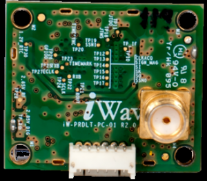
iWave GPS module
iwave GPS module is preferred for this project, the figure of which is shown in fig.2. The main function of this module is to transmit location data to the microcontroller. The connection between IC2 and GPS module is set by connecting transmit pin TXD of GPS to the microcontroller via MAX232. The NMEA data defined an RS-232 communication standard for devices that include GPS receivers. The NMEA-0183 standard which is actually a subset of NMEA protocol is supported properly by the iWave GPS module. This module operates in the L1 frequency (1575.42 MHz) and up to a fixed territory of about 10 meters in the sky, it generates accurate information. For this purpose, the antenna must be placed in the open space and at least 50 percent space visibility is a must.
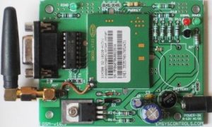
GSM modem
SIM300 GSM modem is implemented in this project and its corresponding figure is given in fig. 3. The main function of this modem is to exchange data. It is a tri-band SIM300; GSM/GPRS engine that works on various ranges of frequencies EGSM 900 MHz, DCS 1800 MHz, and PCS 1900 MHz.In order to set up a connection between the GSM modem and microcontroller, we connect transmit pin TXD and receive pin RXD of GSM modem via MAX232 (IC3) with the microcontroller (IC2). Similarly, port pin PD0 (RXD) and port pin PD1 (TXD) of the microcontroller are connected to pins 12 and 10 of MAX232, respectively.
Power supply
In this project, a 9V battery serves as the main source of energy. Since the microcontroller and MAX232 are powered by 5Volts, we need to convert the supply by using a 7805 regulator (IC1). The presence of a power supply is indicated by LED1.
Software Program of GPS and GSM based Vehicle Tracking System
Because of the program simplicity, we have chosen the “C” language to program the microcontroller and the compilation process is carried out by a software called AVR studio. One must be extra careful to include an exact phone number in the source code so as to receive calls from the SIM card which is set with the GSM set up. To burn the hex code of the program into MCU using PonyProg2000 software, was really difficult. If suited, we can also implement, any suitable tool that can be searched.
As mentioned in the software, to receive the data from satellites we used a GPS module with a 9600 baud rate. The NMEA protocol used in this project is easily decoded by the software. Talking about the protocol, it has a predefined format through which data are transmitted simultaneously by the GPS module to the device with which it is interfaced. The protocol constitutes a set of messages which uses a set of ASCII character and have a defined format that is continuously sent by the GPS module to the interfacing device.
The information is provided by the GPS module or receiver in the form of ASCII comma-delimited message strings. And, each message is coded with a dollar sign ‘$’ (hex 0x24) at the start and (hex 0x0D 0x0A) at the end.
As mentioned already in the previous section, the message content provided by the software output protocol constitutes two different types of data; global positioning system fixed data (GGA) and geographic position latitude/longitude (GLL). For our project, we only require GGA content.
The data format for latitude and longitude details is set as ‘degrees, minutes and decimal minutes’ format; ddmm.mmmm initially. But, since recent mapping technologies demand pieces of information of latitude and longitudes details in the format of decimal, degrees, in ‘dd.dddddd’ along with the respective signs, some sort of conversion process is essential to present data in the desired form. The negative sign is fixed for south latitude and west longitude.
Regarding the development of message string, the NMEA standard defines how to create a new message string with a dollar sign ($) that evolves a completely new GPS message.
For instance:
$GPGGA,002153.000,3342.6618,N,11751.3858,W
Here, $GPGGA denotes the GGA protocol header, second data 002153.000 refers to the UTC time in hhmmss.ss format, third data 3342.6618 is the latitude of the GPS position fixed data in ddmm.mmmm format and the last one; 11751.3858 is the longitude of the GPS position fixed data in dddmm.mmmm format. The alphabets in between direct particular directions as; ‘N’ stands for North and ‘W’ for West.
Being provided with data in such a format, anyone will be able to extract details of the location they prefer to know either by going through a piece of map or going through the software available.
Note: Latest version of AVR Studio might not support the code and show some error. So please use AVR Studio 4.18 for compiling.
CLICK HERE TO DOWNLOAD SOFTWARE CODE
Construction and Testing of GPS and GSM based Vehicle Tracking System
Figure 4 shows the complete circuit with the details of the size of the single-side PCB layout of our project. The component layout of this project is illustrated in fig.5.
Figure 4: Solder Side PCB design
Figure 5: Component Side PCB Design
PARTS LIST OF GPS AND GSM BASED VEHICLE TRACKING SYSTEM
| Resistor (all ¼-watt, ± 5% Carbon) |
| R1 = 680 Ω
R2 = 10 KΩ |
| Capacitors |
| C1 = 0.1 µF (Ceramic Disc)
C2, C3 = 22 pF (Ceramic Disc) C4 – C8 = 10 µF/16V (Electrolytic Capacitor) |
| Semiconductors |
| IC1 = 7805, 5V Regulator
IC2 = ATMega16 Microcontroller IC3 = MAX232 Converter LED1 = 5mm Light-emitting diode |
| Miscellaneous |
| SW1 = Push-To-On Switch
XTAL1 = 12MHz Crystal GPS Module = iWave GPS module GSM modem = SIM300 9V PP3 Battery |


Not Working
This projects is 100% verified, recheck your connection. There might me some connection error or there may be error in uploading software.
Hi
While compiling code after changing the phone number getting error.
which says that UCZS0 and UCZS1 are ‘undeclared’.
please help me
While compiling code after changing the phone number on ‘c file’ getting error.
which says that UCZS0 and UCZS1 are ‘undeclared’.
please help me
I have the same problem with UCZS0 and UCZS1, it says that there are ‘undeclared’
Which version of AVR studio you are using for compiling?
The latest version of AVR Studio might not support the code and show some errors. Please use AVR Studio 4.18 for compiling.
I have some doubts.
1 – My connection is right but when i call GSM there is only a beep sound and the end of the call is out of network. can you please tell me how can i solve it?
2 – This project is available for selling?