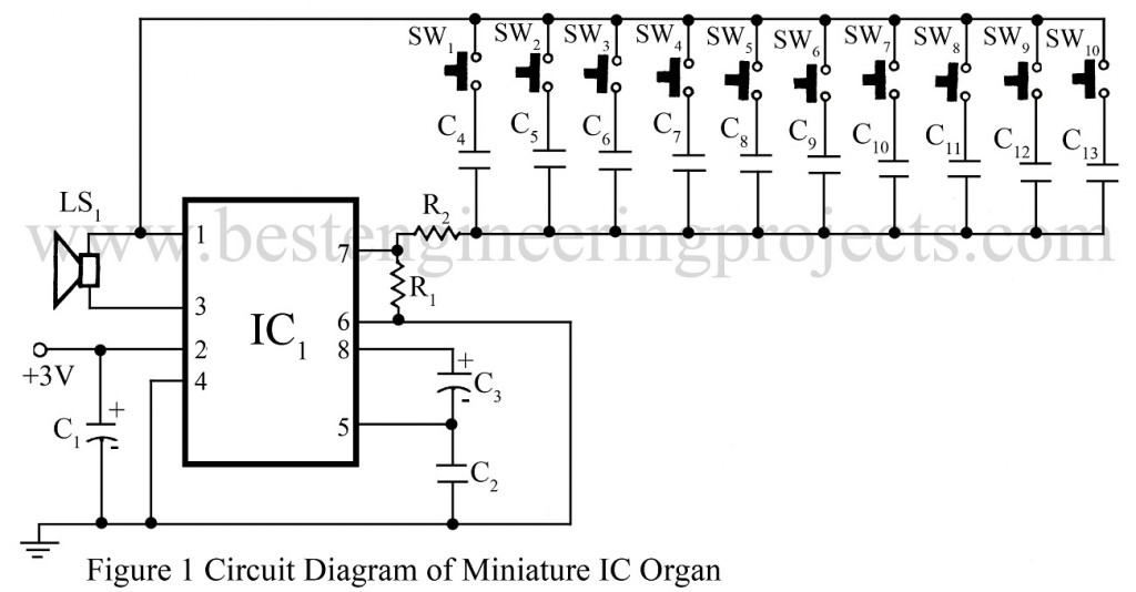
Here is a circuit for an miniature IC organ using 3-volt AF amplifier IC TDA2822. Frequency of the AF sound generated depends on the capacitor between pin 1 and pin 7 of IC. When switch SW1 to SW10 are pressed, different audio tones are heard from the speaker. SW1 to SW10 are small push-to-on switches. Pin 2 of IC is connected to positive terminal of 3-volt battery. Two pen cells connected in series can be used to power this circuit. Satisfactory loud sound will obtained at 3-volt supply.
Note: Capacitors C6, C8, C9, C10, C11, C12 are parallel combination of two or three capacitors to obtained the odd values.
PARTS LIST MINIATURE IC ORGAN
|
Resistor (all ¼-watt, ± 5% Carbon) |
|
R1 = 10 KΩ R2 = 1 KΩ |
|
Capacitors |
|
C1 = 470 µF, 10V (Electrolytic Capacitor) C2, C4 = 0.01 µF (Ceramic Disc) C3 = 1 µF, 10V (Electrolytic Capacitor) C5 = 0.02 µF (Ceramic Disc) C6 = 0.03 µF (Ceramic Disc) C7 = 0.04 µF (Ceramic Disc) C8 = 0.05 µF (Ceramic Disc) C9 = 0.06 µF (Ceramic Disc) C10 = 0.07 µF (Ceramic Disc) C11 = 0.08 µF (Ceramic Disc) C12 = 0.09 µF (Ceramic Disc) C13 = 0.1 µF (Ceramic Disc) |
|
Semiconductors |
|
IC1 = TDA2822 (Dual Power Amplifier IC) |
|
Miscellaneous |
|
LS1 = 8Ω, loudspeaker SW1 – SW10 = Push-To-On Switch |
